Teensy 3.6 fried in vehicle?

Status
Not open for further replies.

BabySpinach

Active member
Hello all,

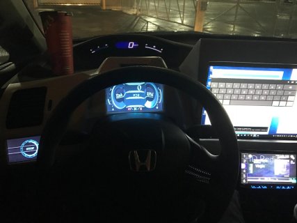
I've been working on a project for about 5 months now that centers around a teensy 3.6. It's an automotive dashboard display. It reads pins via optoisolators and displays everything to dual RA8875 controllers. I have a bench PSU and test setup along with the following power regulation:

One 5v switching regulator 24V input 1A, and one 3.3V switching regulator (the 8 dollar ones from digikey) with manufacturer recommended filters, 15V TVS protection diode, Schottky diode for reverse current protection. All of the digital inputs are behind optoisolators, with no direct connection to any teensy pin, except for a single Analog level shifter that is protected by a 3.3v Zener.

When testing with 12-14V on the bench, the screens turn on and everything works as expected. This has been working since the beginning with no issues.

I attempted to plug in the module into the harness I created in the vehicle, turned the key (and the screen began to boot) and immediately turned on the engine (which restarts the teensy for a second time), the displays flashed for a very short moment, and nothing happened! The teensy now appears to be dead! I've checked all power sources and 5v is at the input, the teensy just doesn't blink or do anything. It's no longer showing up at all as a COM device. I can't get it to do anything.. I have a USB cable I use for uploading with a clipped 5V wire. Even with external teensy power to the VIN, this cable doesn't work. With a direct 5v powered cable, there is still no teensy life.

Do I need a long delay when booting anything that reads from a SD card and loads SPI? Unless there's something obvious I'm overlooking, I think I'll need to buy another Teensy.. I'd like to not fry the next one. Is there something I need to do to prevent this?? :(

I've attached the setup and loop code.
 

Attachments

  • WorkingBMPRA8875WithFont-12.ino
    22.1 KB · Views: 133
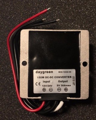
I use this PSU in my setup:
$_57.jpg

input is 8-40 volts, and output is a solid 5v 30A
it runs 24/7 in my setup and most importantly, survives cranks.
been using it for 2+ years without issues, and the voltage never fluctuates.
it's sealed in a waterproof epoxied aluminum case and remains cold to the touch, using it on a teensy 3.5 and 13 i2c devices, 11 spi devices, and several other IC chips (analog switches, optocouplers, port expanders, triple canbus transmit/receivers etc), 2 lcd screens, servo, mosfets, etc
37ffeea89c.jpg

my best guess is your powersupplies didnt account for the "brownouts" during "cranking" and their voltages went crazy
no issues here using this PSU...

you dont need to see a com port to program teensy but you can try the recovery

hold the program button on teensy before plugging it into your pc, once fully plugged in, let go the button, and try to upload the blink example
again, just because you dont see the com port doesnt mean teensy doesnt work, it uses USB for uploading, irregardless of serial port.
 
Last edited:
"immediately turned on the engine (which restarts the teensy for a second time),"

that means your psu's are not designed to sustain a voltage during brownouts/cranking. this is very bad for automotive field. the PSU above has a wide input range of 8-40V, so you can use it for cars (12V), or trucks (24V)

what did you use the 3.3v switching regulator for? better to use the one on the teensy, and just supply 5V to it's VIN line. Also I try not to use the MCU pins, most of the wiring goes to the MCP23S17 & MCP23017 port expanders junction, the only wiring I keep at the mcu is the SPI, CS, I2C, and only one GPIO used that goes to the alarm's hood line switch to ground it out, to prevent remote starts. theres a proximity switch and 4 hall effect sensors surrounding the shifter, so I've also got gear position on the lcd. if the mcu is disconnected, power loss, or shifter is in a position, the hood line will always stay LOW (failsafe)

as a recommendation, use the T3.5 for the car, some of the circuits are 5V (like my HVAC circuit, which I digitally converted to touch screen) so you get the benefits of both the 3.3 and 5V ranges.
 
Last edited:
Thanks for the reply! Great info! I use the 3.3v regulator to power dual 7 inch display screens. I'm hoping they have a 3.3v version of these too!
 
No luck on the reset. It seems to be completely dead. The USB port actually burned me when I touched it on the Teensy just after about 30 seconds of on time. What I don't understand is how this happened. I have what I thought was a very beefy power setup with the 24v regulators, plus the 15v diodes. I also took every precaution to prevent something like this from happening. I'm not seeing a 3.3v version of that PSU. :(
 
Beefy may not be the perfect answer here. There are three possible modes of death:

Operating during brown out - Have been some prior cases where a Teensy has died due to extended operation below 3.3V but high enough for clock to run, which at least in other CPUs leads to incorrectly read/executed commands randomly hitting registers until something destructive is set - preventing brown out through good regulation is first step, followed by brownout detection and placing CPU in reset/safe state for duration is the second layer.

Poor regulation - A high current PSU may assume stable supply but variable load so a nominal 3.3V output may fall sharply under cranking, then as regulator opens up the taps to stabilise the output supply cranking stops and supply voltage returns the nominal 3.3V overshoots high and wreaks havoc. Idea is to stage regulators, and keep sensitive parts on their own PSU capable of soaking wide supply side swings, hence comment above about supply the Teensy with 5V and letting onboard reg be the final shield (though even it goes toes up much past 5.5V). Can have similar problems if things like relays or high current LEDs share a PSU with your CPU.

Noise/EMI - It's also possible for the DC supply to be steady but the RF noise from ignition to reach the micro and either disrupt it's operation or just outright cook it - suspect not your problem here but common cause of random resets. Solution is sensible wiring design (no accidental tuned antennas) and liberal sprinkling of capactive filters and RF chokes.
 
What I don't understand is how this happened.

We might be able to help you figure out, if you show us *exactly* what you actually built. Diagrams and photos help. Don't tell us what you made (or intended to make), actually show us what you really built.

And FWIW, 12V electrical systems in cars are pretty terrible when the engine is on. High voltage spikes are common. It's tough to build power supplies to withstand such input power.
 
ive purchased a few of these 12v 6a, and 5v 30a psus, here is a fleabay link for a 3.3v 30a version:
this is a searched link im in no way affiliated with them

cheapest one there is a 3.3v 20a is 18.89$ usd

http://m.ebay.ca/itm/Waterproof-DC-...3Abb4eda0815c0abc01eef4ab2fffd33cf%7Ciid%3A16

if you really want 30a the cheapest is $22.30

http://m.ebay.ca/itm/DC-12V-24V-36V...3Abb4eda0815c0abc01eef4ab2fffd33cf%7Ciid%3A23

and if anyone is wondering, my entire setup is running off a 5v 30a version, only one psu
i would still get the 5v 30a version and use that for the teensy vin (im not even sure the 3.3v will be good enough for teensy VIN thats why i recommend you get both 3.3 and 5v version). 5 volt for teensy vin, and 3.3v for your lcd, just so the teensy can use it's own regulator, and not touch the 3.3v pins directly with any automotive psu
both have free shipping, but as usual you need to wait for them via snail mail

im glad my displays use 5v input :)
 
Last edited:
Do you think I could just get something like this:

http://www.ebay.com/itm/8-40V-to-12...fbd7cd4&pid=100005&rk=2&rkt=6&sd=351905870577


It's a 12v to 12v.

My current buck converters are rated 8-24v input too.

ive purchased a few of these 12v 6a, and 5v 30a psus, here is a fleabay link for a 3.3v 30a version:
this is a searched link im in no way affiliated with them

cheapest one there is a 3.3v 20a is 18.89$ usd

http://m.ebay.ca/itm/Waterproof-DC-...3Abb4eda0815c0abc01eef4ab2fffd33cf%7Ciid%3A16

if you really want 30a the cheapest is $22.30

http://m.ebay.ca/itm/DC-12V-24V-36V...3Abb4eda0815c0abc01eef4ab2fffd33cf%7Ciid%3A23

and if anyone is wondering, my entire setup is running off a 5v 30a version, only one psu
i would still get the 5v 30a version and use that for the teensy vin (im not even sure the 3.3v will be good enough for teensy VIN thats why i recommend you get both 3.3 and 5v version). 5 volt for teensy vin, and 3.3v for your lcd, just so the teensy can use it's own regulator, and not touch the 3.3v pins directly with any automotive psu
both have free shipping, but as usual you need to wait for them via snail mail

im glad my displays use 5v input :)
 
you could get that too, i have a few of them but dont use them, but still, 12 volt would be hard on a linear regulator, and if your buck converter is the reason you fried it you should still not piggyback it off a new psu and change it altogether to something more reliable, dont use your bucks, change them, but from experience, that epoxy sealed psu would be more reliable than off the shelf buck converters not meant for vehicle field
 
These are the regulators I'm currently using, FYI: R-78C3.3-1.0, and R-78C5.0-1.0

Ok, but exactly *how* did you use them? (photos are best to show us)

For example, if you look at page 2 of the datasheet you'll see recommendations about 2 capacitors and a zener diode. Did you use those parts? How was everything actually connected?

I should mention, at first glance these look very similar to a Traco part that caused other people a lot of trouble years ago.
 
We might be able to help you figure out, if you show us *exactly* what you actually built. Diagrams and photos help. Don't tell us what you made (or intended to make), actually show us what you really built.

And FWIW, 12V electrical systems in cars are pretty terrible when the engine is on. High voltage spikes are common. It's tough to build power supplies to withstand such input power.

http://imgur.com/a/aX5Y8

This album has some fluff, but it shows the circuit boards in pretty good detail. I don't have an exact schematic. It uses dual RA8875s on a Tristate buffer, along with the bucks I listed above. There is also a Sparkfun level shifter. The Teensy 3.6 is powered directly to the VIN via the 5V buck. The 7 in screens/ RA8875s are powered directly from the 3.3V buck. All other pins are Optoisolators, or SPI. There is one voltage divider with an input voltage, but it's Zener protected.

The power regulators have the following protection:

Protection diode:
Schottky 20V with Fv of 450mV @ 1A

TVS Diode:
15.3V Reverse Standoff
 
I've purchased two Teensy 3.6 replacements. I'm going to hand test each 12v opto and voltage divider to see if there's potentially a short that's sending 12v to a pin. I really won't know if I also killed my RA8875 controllers or displays until I get the new teensys in.
 
please dont use voltage dividers in a car, thats asking for trouble
a simple quad PS2501-4 opto and series resistors (~1.5K) and diodes is all you need

and if you want to be really safe, hit up some mcp23017 (i2c) or mcp23s17 (more reliable, faster, spi) expanders, they can take a beating at the gpio pins, a teensy cannot. It's even possible to short the pins on them and it still survives.
 
Last edited:
please dont use voltage dividers in a car, thats asking for trouble
a simple quad PS2501-4 opto and series resistors (~1.5K) and diodes is all you need

and if you want to be really safe, hit up some mcp23017 (i2c) or mcp23s17 (more reliable, faster, spi) expanders, they can take a beating at the gpio pins, a teensy cannot. It's even possible to short the pins on them and it still survives.

I understand. The V/DIV is a 5v to 3.3v step from a regulated TCU source. That's the only reason I used it.
 
I wanted to give an update. My new Teensy's won't arrive until today, but last week, I went to check the vehicle's fuel level by reading the ohms on the fuel sensor wire and received a strange reading. I decided to check the value with the vehicle engine on or on accessories and was unable to get a measurement with the meter. For kicks and giggles, I tried measuring the voltage on the pin and read a 14v signal. :( This means the wire I thought was the fuel tank sending wire was actually a 12-14v HOT accessory wire. This wire was connected to the teensy on a voltage divider. 14v into a 3.3v input. I think I found the problem. :(

I wanted to thank you guys for attempting to troubleshoot my mess. :)

I'll be programming and installing a new teensy this evening.
 
Status
Not open for further replies.
Back
Top