LED Strip Display Code Issue: Teensy 3.2 + OctoWS2811

Status
Not open for further replies.

codereq

Member
Hi,

Having some issues getting an LED Strip Display running. I used the instructions: here, which is a fairly unique build but was actually reproduced by a PJRC user here. I can't get the code to work properly. Here's some background:

Standard Setup Stuff
  • (30) WS2812B strips; 60 LED's per strip; 1800 total
  • (3) 50A 5V power supplies
  • Teensy 3.2
  • OctoWS2811 Adapter
  • Data transferred in the regular snaking pattern (LED_LAYOUT 0)
Interesting Stuff
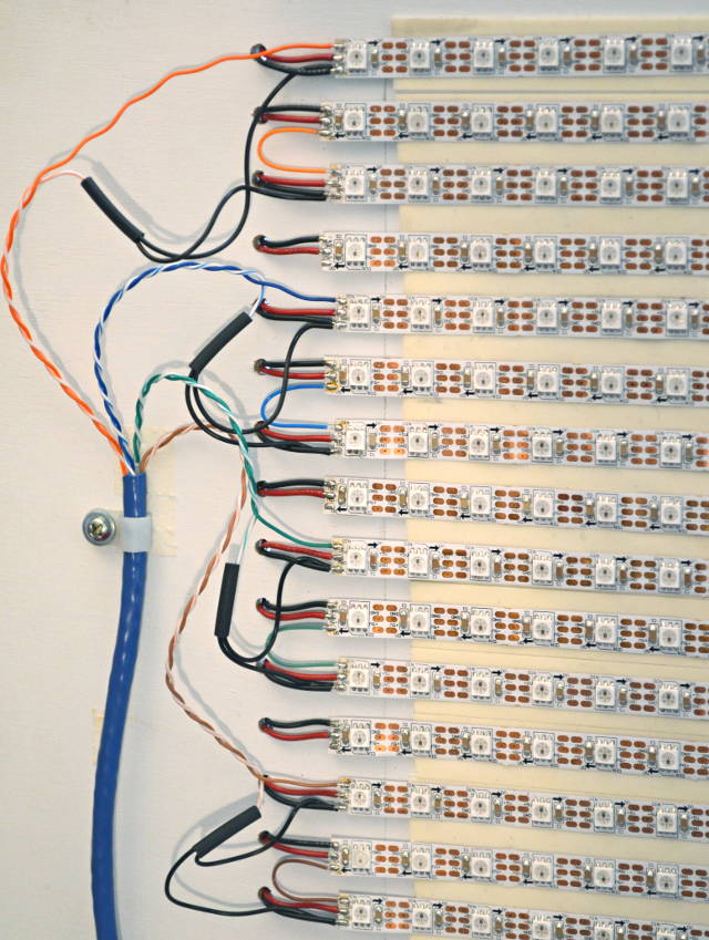
  • Uses CAT6 pairs to power strips. Each UTP color has a female T Connector soldered, and every other LED strip has the male T Connector end to make it very easy to take apart. The original maker told me he used 24AWG CAT5; I got 23AWG solid copper CAT6 to try to get a bit more current.
  • Data inputs placed at strips 1, 13, and 25
I'm running all code included when I downloaded Teensyduino a couple months ago. I realize I only have 30 strips which isn't divisible by 8, but my understanding is that the only issue is that the imagery will be cut off 2 rows early, and the code runs/uses memory as if the final 2 strips are there. I didn't alter the code anywhere it mentioned WS2811 because my understanding is that it should be compatible, and I didn't find any posts recommending code changes.

The issues I've encountered are all similar:

  • When I run the BasicTest.ino, the only strips that light up are the data input strips, and the strip connected below it (strips 1-2, 13-14, 25-26). If, at the top of the code
    Code:
    ...
    #include <OctoWS2811.h>
    
    const int ledsPerStrip = 120;
    
    DMAMEM int displayMemory[ledsPerStrip*6];
    int drawingMemory[ledsPerStrip*6];
    ...
    I alter
    Code:
    const int ledsPerStrip = 120
    to
    Code:
    const int ledsPerStrip = 720
    all strips light up, but at a complete crawl. It can take a full minute or longer for the colors to switch.

  • If I run PlasmaAnimation, an almost identical problem. The only strips that run are the data input strips, and the strip connected below it (strips 1-2, 13-14, 25-26). If, at the top of the code
    Code:
    ...
    #include <OctoWS2811.h>
    
    //OctoWS2811 Defn. Stuff
    #define COLS_LEDs 60  // all of the following params need to be adjusted for screen size
    #define ROWS_LEDs 16  // LED_LAYOUT assumed 0 if ROWS_LEDs > 8
    #define LEDS_PER_STRIP (COLS_LEDs * (ROWS_LEDs / 8))
    ...
    I alter
    Code:
    ROWS_LEDs 16
    to
    Code:
    ROWS_LEDs 96
    all strips light up, but at a complete crawl.

  • If I run VideoDisplay.ino + Movie2Serial.pde, a slight change: the strips that run are the data input strips, and three (3) strips connected below it (strips 1-4, 13-16, 25-28).

I'm obviously not great at coding, so I'm glad to try any suggestions. I ran into similar issues when running the altered code the original maker provided, so I wanted to address the issues with the basic code first.
 
Can you show us (with photos) how you actually connected everything? Don't tell... show!

My best guess is something isn't connected quite right. But without actually seeing, very hard to say.
 
Photos provided below, and please let me know if I've left anything out. I've gone through several rounds of testing and the exact same problems presented each time.

The data lines are connected exactly as shown in this diagram, orange at top, blue in middle, green at bottom. The power wiring is next to it. The original maker's design is for 36 strips, which I've reduced to 30. I've connected the strips identically, except with the bottom 6 strips removed. As noted above, it's my understanding that the code must be written with a multiple of 8 strips, but any "unused" strips still get assigned memory.
View attachment 10995 View attachment 10997
If I switch the order of the data lines and run BasicTest.ino, the strip sections will update in the "wrong" order, but they still all update.

The data line wires are soldered to JST connectors. Solid color wires go to the JST's data line, white/color mixed wires go to JST's ground. Here is the maker's hi-res photo, and my version:
View attachment 10996

This is Strip 1 connected to data and power (top left of the diagrams). The LED strip is to the right of the photo.
LED Display First Strip Data and Power.JPG

This is Strips 1-2 connected to each other with data and power (top right side of the diagrams). This continues for every pair of strips, as shown on the right side of the the diagrams. The strips came pre-soldered with the JST connectors and power/ground wires. Upon delivery, I tested each strip individually to make sure they lit up and updated properly.
LED Strip Display - Strips 1 and 2 connected.jpg

This is strips 2-3 connected (left side of the diagram). Note that strip 2 connects data with strip 3, while strip 3 is also connected to power. It continues this way on the left side (4-5, 6-7, 8-9, 10-11), and 12 isn't connected to anything. Repeat for the left side two more times, as shown in the diagrams above.
LED Strip Display - Strips 2 and 3 connected.jpg

If it helps to see it all together, this is the original maker's completely plugged in.
 
The original maker pointed out to me that PJRC's original code is for a very different wiring scheme than he produced, so I ran a full gamut of testing with his versions of your code. The results were very similar, with a small variation. Using PJRC code, the only strips that light up are the data input strips, and the strip connected below it (strips 1-2, 13-14, 25-26). Using his altered code, the strips that lit up were the data input strips, the three below each input strip, and 16 LEDs on the strip below those - here's a photo to help: Link.

I've picked up a new Cat6 cable to create a new data cable, and a new micro-b cable to try to rule those out as the causes.
 
I noticed my Teensy + Octo with Headers doesn't look the same as anywhere else I've seen. Given that, and that the strip multiplying effect isn't taking place, here are pictures of my Teensy 3.2 ordered with pins, and OctoWS2811 with sockets (picture). And just in case, attached from front (picture) and back (picture).

Not sure if it will help, but here's closer pictures of my wired connections. Left end (picture) and right end (picture). The JST connectors were pre-soldered by the factory.

Other attempts:

  • Made a new data cable and acquired a new micro-b cable, then ran testing with them. Same results.

  • Downloaded the OctoWS2811 library and examples again. Same results.

  • Tried to run the FastLED Octo example (FastLED/examples/Multiple/OctoWS2811Demo/OctoWS2811Demo.ino). Line 5 & 6 that define LEDs per strip & number of strips:
    Code:
    #define NUM_LEDS_PER_STRIP 60
    #define NUM_STRIPS 8
    Whatever number NUM_LEDS_PER_STRIP is set to is how many LEDS light up at each data input strip (1, 13, 25). So if it's 60, it's three strips' worth. If it's 70, it's the data input strip + 10 LEDs looped back the other way. Changing NUM_Strips has no effect.
 
Not sure if it will help, but here's closer pictures of my wired connections. Left end (picture) and right end (picture). The JST connectors were pre-soldered by the factory.

Look like you've misunderstood the wiring. These LED strips are connected wrong.

Teensy only provides the data for the LEDs. They need both data and power, a *LOT* of power.

First of all, you need a large 5V power supply. The USB power for Teensy can't possibly be used for this large number of LEDs. USB power can usually only be used for about a dozen LEDs. For a big LED project, it's best to plan about 0.05 amps per LED. So if you have 1800 LEDs, you'll need 5V power supplies capable of 90 amps.

Your photos look like you've connected the data signals to the power lines, and you don't seem to have any power supply connected at all.

The most important thing is good power wiring. You should run short wires directly from the power supply to the red (+5V) and white (GND) wires for every strip. If you have 30 strips, that means 30 pairs of wires. If the strips are "long", you may need to run the power to both ends of every strip. That means 60 pairs of power wires. That's *not* excessive. Your LEDs will use approx 90 amps of current if you turn them all on fully white! Normally the wires from the power supply to the LED strips should be #22 to #18 gauge. Long power wires should be avoided.

When every strip has power connected to white and red, then you connect the Teensy signals to the green (DATA) and white (GND). Yes, that means two wires will connect to each wire wire where data comes in.

Those connectors that were pre-installed on the strips can be useful for connecting the data output from one strip to the input of another. But at the inputs, you'll probably need to cut them off. Maybe you can use the male connector from the end of a group to plug into female connector at the input. Just know the connectors aren't necessarily the way you need things. You don't simple plug them all together and then match up the remaining wires by color. Those dangling red and white wires are meant for you to connect to a big power supply. The connectors allow chaining strips, but at the beginning you will need Teensy to connect to the green and white.

Hopefully this all means some sense?

Here's the photo from the OctoWS2811 page showing correct wiring. Notice how a red and black wire from behind the board (where the power supplies are mounted) connects right to the LED strip, and the data wires also connect to the GND inputs. This is the proper way. You can do it through those pre-installed wires and connectors, but it must be similar for things to work.

octo28_adaptor_7.jpg


BTW: your Teensy looks fine. Many of the photos online show Teensy 3.0 or 3.1, since this LED stuff was mostly developed in late 2012 and early 2013. You simply have the newer Teensy 3.2. It does work.
 
Hi Paul,

Thanks for taking the time to look into the issues.

First of all, you need a large 5V power supply. The USB power for Teensy can't possibly be used for this large number of LEDs. USB power can usually only be used for about a dozen LEDs. For a big LED project, it's best to plan about 0.05 amps per LED. So if you have 1800 LEDs, you'll need 5V power supplies capable of 90 amps.
I have three (3) 5V 50amp power supplies running the project. The USB is only providing power for the Teensy.

Those dangling red and white wires are meant for you to connect to a big power supply.
Sorry the pictures were unclear, that's exactly how I have it wired. I think it looks like I didn't because of (this picture). CAT 6 is used for both data and power; the ones connected to T Connectors are the power lines. Using the dangling white/red wires, the power CAT 6 wires connect to every other strip on the left side, per the diagram (image). As you noted, the the JST connection is only used for data and the data's grounding.

From reading a lot of other advice you'd given, I was pretty concerned about getting enough power to the strips. I proceeded with the build noting that two people successfully built the display using the directions. Altering your version of basicTest.ino, I have been able to get the all of the LEDs to light and maintain without the wires heating up. I don't have a picture of that, but I have a picture running the build's altered code erroneously (photo). Solid copper 23AWG CAT 6 are used for power and data connection. The AliExpress seller told me the LED strip's dangling red/white wires are 20AWG, for whatever that's worth.

Have I missed any of your concerns? On Tuesday I should be able to set it up again and take more photos, so please let me know if I can take any to clarify. This is my first major project so I'm fully ready to accept I screwed up build.
 
Hi Paul,

Could you let me know if I missed any insights from your previous post?

To be sure/safe about the pre-soldered LED strip wires, I cut the heat shrink and took a look (picture). It appears to be wired correctly.

Thanks
 
After running further testing, I was able to get at least some of the designer's altered Octo test sketches working. I still haven't been able to get your original code working, but that is not a surprise due to the strange wiring scheme used. Given that, I'll go to him for help. I appreciate your help in all of this.
 
Coming back for help as I think you guys might have some insight as it involves consistent Teensy crashing. After working with the original author, I was able to successfully complete a two hour "light show" video stress test. Unfortunately, I've been unable to replicate the results. Now, whenever I run the video, the Teensy either freezes (video on LEDs freezes, Teensy LED stays solid orange) or totally crashes (video on LED freezes, Teensy LED off entirely) after about 4-5 minutes. If it freezes, I can restart by re-uploading videoDisplay.ino. If it crashes, I need to unplug and re-plug the Teensy.

I'm running two pieces of modified PJRC code. First, a modified version of videoDisplay.ino. Second, for Processing I run a modified version of movie2serial.pde called screenCapture.pde. The original author just updated the Processing code and was kind enough to create a Github branch just for my code. The updated code fixed an image mirroring issue, but the freeze/crash issue remains. We're both a bit baffled.

I tried swapping out the USB cables and plugging in to different USB ports. Could it be a power issue? A Teensy or Octo issue?
 
With just a quick look at the code, I see this:

Code:
    while(Serial.available()<=0);
    r = Serial.read();
    g = Serial.read();
    b = Serial.read();

This should almost certainly check for Serial.available() < 3, since you're reading 3 bytes.
 
Thanks for looking into it. If I change videoDisplay.ino to use "Serial.available() < 3" the Processing code runs, but doesn't actually show anything on the LED Display. The Processing code opens a preview window on the desktop that should reflect what's on the LED Display, but nothing appears.
 
Status
Not open for further replies.
Back
Top