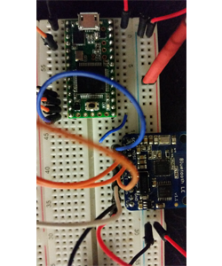
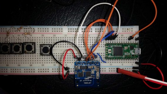
This circuit killed 2 teensy 3.1's , what did I do wrong ?

Status
Not open for further replies.

lynton

Active member
Hi, I managed to kill 2 teensy 3.1 with the circuit pictured.

I had hooked up an adafruit nrf8001 ble to a teensy 3.1 and all was working well for a few hours

Then I rewired it to make some room and changed 1 thing only. (I think)

The ground from the BLE had been going to a spare ground pin on the teensy but instead, I ran the BLE directly to the ground rail.

I figured that both teensy and BLE were connected to same ground supply although no longer directly connected to each other.
Could this be the problem ?

In the photo the red heart shrinked wires run to a solder station voltage supply that was set to and checked at 4.2v.

I'm still on a learning curve and grounding is something that still confuses me I have to admit. Is what I did wrong ? Or is something else going on here ?

Thanks for any help, I needed to figure this out before I can move on without killing any other poor defenceless teensy's.

Lynton.
 
Hi, I managed to kill 2 teensy 3.1 with the circuit pictured.
Sorry can't find how to add a photo to this post, sure I did this once before here, but perhaps that has changed.

Anyway the main question is :

Was my changing the ground set up the problem here ?

Thanks.
Lynton
 
sorry still unable to upload the photo,
just get back dialog :
"forum.pjrc.com says upload of file failed"

file is a jpg and only 3 and a bit mg in size is there a limit or something ?
 
teensyble.png
finally figured it out, converted to a smaller png file.
 
JPG is fine, and generally lets you upload larger resolution at the same file size. That PNG is kind-of small resolution; I can't read what the labels on the pins are. (Not to mention the wiring is in the way, so I couldn't read them anyway.)

In general, running multiple connectors to the same GND rail should work fine. The way you'll bust a Teensy is if you:

1) Over-volt some pin. The analog-only inputs are not 5V tolerant. The 3.3V rails are outputs, and should not have anything fed INTO them. The Vcc is supposed to go to 6.0V; if you have an unstable input that may "spike" higher than that, that could be a problem. If you connect long wires, there may be inductance in the wires that cause large voltage swings; see https://www.pololu.com/docs/0J16/all

2) Over-current some pin. Trying to drive a "voltage in" with a "digital out" or shorting a pin that is driven high would be examples. I believe Teensy pins are generally specified at 8 mA tops.

3) Various EMI and EMF problems. Especially when turning things on and off, wiring can see all kinds of noise. Also, connecting USB will add another component to the mix, as well as wiring that can pick up EMF. Does your USB cable have a "choke" inductor right before the micro-USB connector? Most cables are cheap and do not, and this will make them more likely to transmit any problems they may pick up.
 
Without seeing a larger photo and a schematic, it's going to be hard to tell. However, here are some thoughts:
- Are you absolutely sure the teensies are dead (reminds me of a joke, but...)? As the previous poster said, Teensies are pretty robust.
- The BLE transmits an RF signal, so you *might* be dealing with an RF interference issue, which *could have* been exacerbated by moving the BLE GND line to a different point, thereby creating what is known as a "ground loop". A ground loop can allow large currents to be induced into the circuit, such that the Teensy ground and/or the BLE ground aren't what you think they are. In general when dealing with RF circuits, it is a very good idea to have all grounds go to the same physical point

Just my $0.02

Frank
 
Thanks @jwatte, your response has helped.

Particularly the link to the article on voltage swings.

The first thing I will do is put in a switch on the breadboard instead of just plugging in the wires, which apparently exacerbates the voltage swing.

The power wires are short and simply soldered to two header pins which I then plug into the breadboard to power up, but its a fairly loose fit and may be helping cause some bouncing..

I think I'm curious enough to get an oscilloscope now :cool:
I'll do some tests and see if I can locate some spikes in the setup I have.

Now that I know the hook up is OK, i think its most likely the cheap clone solder station with power supply that I'm using may be the culprit, combined with me plugging in the power wires.

Even though the voltage out of it looks accurate, it may well be spiking at the very start. I tried measuring voltage from it with a meter and I thought I briefly saw 8v as the meter settled in the first half second or so but I don't know if it was just the meter settling down or not. I compared with a 4.2 v lipo and it looked much the same also showing about 7v very briefly at the start.
After the first bit of swing it seemed steady at 4.2v

I don't think the other things you mentioned are the cause, I use a standard USB cable, but the USB power is isolated by severed vusb pads on the teensy anyway, and both components use 3v logic so overvolting looks unlikely too.

Now off to do some research on a good oscilloscope to buy :)
 
Frank, Sorry for bad photo but the one I took was 3mb and had to be shrunk to 360k to pass the upload Nazi. I will try again tomorrow, its very late here now.

Pretty sure teensys are dead. They got hot and the current draw jumped from a few mA to about .5 A. They are no longer recognized on computer USB .

The ground both go to the ground rail . do you mean they should be mover closer together on the rail ?

Yes, they should go to the same physical point, and the wires themselves should be as short as possible, although to tell the truth, I really don't think that RF induced currents in the ground lines killed your Teensies. I have seen this happen when dealing with high-power RF systems, but I don't think the BLE can produce that sort of energy.

I think it is much more likely that when you moved the BLE ground to the rail, that you actually moved it to the VCC rail instead, or moved the Teensy ground to the VCC rail. I saw from the photo that you are using a prototype plug-board, and sometimes the ground and VCC rails aren't where you think they are ;-)

Frank

PS: I have a Tektronix 2236 scope, and I love it. This scope was originally designed to compete for a military portable scope contract, so it is small, light, and pretty rugged. They can be had for a couple of hundred bucks on eBay. Even better, this scope fits very nicely on a Tektronix type 200C Scope-Mobile :)
 
OK finally got a decent shot at a low enough resolution to keep under the 360k limit.
I am going to check the voyages on all the pins next , as someone here suggested , perhaps the breadboard has a short somewhere.
IMG_20170724_145230.jpg
 
I took this video of connecting the power supply. The meter shows a very brief reading of 8.4v before settling to 4.3. The supply is set to 4.2v.

At first I thought that this was it but then I tried the same test using a 4.2 lipo battery supply which still showed an initial spike of 7.4.

So now I'm not sure ... Could this just be the meter settling down ?
Is there perhaps something with the wiring causing any supply to spike ?

If it is a spike (and not just meter settling in) would this be enough to fry a teensy 3.1

Thanks
Lynton


Your meter looks like it is just behaving like a typical auto ranging meter. Until it settles down, you can't believe anything that shows.
In your picture, the black ground wire in the lower right corner looks funny. It appears to be bent and perhaps not really plugged in. If this wire is open, your teensy will be missing a ground and will not run. Maybe your teensys are ok?

Make sure the other end of your power supply is connected the way you think it is. When things burn, it is usually because the power was hooked up backwards.

When you rewire, you want to remove the power first. You don't say in the first post if you were changing things with the power on or off. You should wire up everything, then turn on the power. In the video, you plug in the power cable with the supply turned on. Maybe you plugged it in backwards when you killed the teensy? If you can, turn on the power with a switch on the power supply and leave it wired up. If your power supply has current limiting, turn it down until you figure out what is wrong. Set the current limiting just high enough for the circuit to run.

Also, temporarily remove the BLE from the board, leaving just the Teensy. Until you figure things out, you want the smallest number of variables possible. Make sure you can run that Teensy reliably (like, for hours) without any problems before you even think of adding the BLE back in ;)

Frank
 
Your meter looks like it is just behaving like a typical auto ranging meter. Until it settles down, you can't believe anything that shows.
OK thanks, that explains why it also happens with the lipo.

maybe your teensys are ok?
no they are quite dead, attaching power to vin causes them to draw .5A and heat up.


When you rewire, you want to remove the power first. You don't say in the first post if you were changing things with the power on or off.
Power was off when moving wires around


Thanks everyone for all the helpful advise, i learnt a bit as you always do when things go pear shaped.

Its a bit frustrating as i guess that I will never know what happened,

I am as certain as I can be that I did not hook up the power backwards, i am particularly paranoid about that and especially not the second time. I was extremely cautious that time.

I also removed the boards and checked for voltage on all the wires to check for breadboard faults and all seemed OK.

I'm all out of ideas ( and teensys ) now,

My main concern is whether I can trust the power supply or not, it is part of the solder station i have which is a cheap clone but otherwise seems fine, i have only recently started powering from it because it has a current meter useful to see how much current a circuit is drawing.

It did power the circuit fine for a few hours the first time.

But perhaps every so often there really is a spike, can anyone suggest an easy way to test it ?

Thanks again for you time and advise
Lynton.
 
OK thanks, that explains why it also happens with the lipo.


no they are quite dead, attaching power to vin causes them to draw .5A and heat up.


Power was off when moving wires around


Thanks everyone for all the helpful advise, i learnt a bit as you always do when things go pear shaped.

Its a bit frustrating as i guess that I will never know what happened,

I am as certain as I can be that I did not hook up the power backwards, i am particularly paranoid about that and especially not the second time. I was extremely cautious that time.

I also removed the boards and checked for voltage on all the wires to check for breadboard faults and all seemed OK.

I'm all out of ideas ( and teensys ) now,

My main concern is whether I can trust the power supply or not, it is part of the solder station i have which is a cheap clone but otherwise seems fine, i have only recently started powering from it because it has a current meter useful to see how much current a circuit is drawing.

It did power the circuit fine for a few hours the first time.

But perhaps every so often there really is a spike, can anyone suggest an easy way to test it ?

Thanks again for you time and advise
Lynton.

Lynton,

I use the 'Mean Well' fixed voltage power supplies a lot. They are very compact, noiseless (at least acoustically - don't know about electrically), and very cheap. See this page for a representative module.

Frank
 
But perhaps every so often there really is a spike, can anyone suggest an easy way to test it ?

A fun way to test it would be to hook it up to power something you don't really care about. Then using an Arduino, connect an analog pin to the power supply output via a 1k resistor and connect ground to ground. Then write a sketch to measure the voltage output perhaps sampling once every millisecond. You could capture min and max voltages, measure the ripple, etc and print them out on the serial connection. For a power up spike test, you would want to sample as fast as you can and capture data to an array and then print out the data after the test is done.
 
If it is a spike (and not just meter settling in) would this be enough to fry a teensy 3.1

Yes, a spike over 6V even for a very short duration can kill a Teensy 3.1.

This issue and the need for more current at 3.3V to power Ethernet and ESP were the main reasons we made Teensy 3.2 with a dedicated voltage regulator chip.

Still, this isn't conclusive about what actually went wrong. It could have been many possible things. Accidentally touching 5V power to the 3.3V pin also destroys a Teensy.
 
A fun way to test it would be to hook it up to power something you don't really care about. Then using an Arduino, connect an analog pin to the power supply output via a 1k resistor and connect ground to ground. Then write a sketch to measure the voltage output perhaps sampling once every millisecond. You could capture min and max voltages, measure the ripple, etc and print them out on the serial connection. For a power up spike test, you would want to sample as fast as you can and capture data to an array and then print out the data after the test is done.

that does sound like fun , I have some clone pro micros around Ill give that a try and report back findings.
 
Yes, a spike over 6V even for a very short duration can kill a Teensy 3.1.

This issue and the need for more current at 3.3V to power Ethernet and ESP were the main reasons we made Teensy 3.2 with a dedicated voltage regulator chip.

Still, this isn't conclusive about what actually went wrong. It could have been many possible things. Accidentally touching 5V power to the 3.3V pin also destroys a Teensy.

thanks paul.

I take it this means that Teensy 3.2 is better equipped to handle a voltage spike. Is that correct ?
 
thanks paul.

I take it this means that Teensy 3.2 is better equipped to handle a voltage spike. Is that correct ?

history back . . .

Today we're happy to release Teensy 3.2.

http://www.pjrc.com/store/teensy32.html

Version 3.2 is a minor upgrade to Teensy 3.1. The main change is an improved 3.3V regulator, to allow Teensy to directly power ESP8266 Wifi, WIZ820io (W5200) Ethernet, and other power-hungry 3.3V devices.

We're specifying Teensy 3.2's power output at 250 mA and the maximum voltage input at 6 volts, due to PCB thermal dissipation limits. However, the actual regulator chip is capable of up to 10 volts input, and up to 500 mA output. These higher limits are intended to allow Teensy 3.2 to be more rugged when used with non-USB power sources which aren't well regulated 5 volt sources.

Teensy 3.2 is fully compatible with all shields and add-on boards designed for Teensy 3.1. It preserves the same size, pinout, and processor as Teensy 3.1.

The bootloader chip is also changed from Mini54 to KL02 (the same as Teensy-LC). A full schematic is available:

http://www.pjrc.com/teensy/schematic.html
 
However, the actual regulator chip is capable of up to 10 volts input

ah ha that sounds like want I need, I'm guessing my sloppy connection methods pushed the 3.1s over the edge and that the 3.2 s will be much harder to kill.

thanks for that info, I feel much more comfortable about getting a 3.2 replacement now.
 
Status
Not open for further replies.
Back
Top