Teensy 3.6 vs Arduino Issues with Adafruit Bluefruit LE SPI Friend

Status
Not open for further replies.

mechadi

Member
I’m working on this project where I need BLE functionality. The Adafruit Bluefruit LE SPI does everything I need it to do (the Nordic UART service is pretty handy and has accompanying apps) and works flawlessly when I test it on an Arduino Nano. As soon as I hook it up to my Teensy 3.6 it starts being erratic. I’m running the example blueart_datamode.ino given with the Bluefruit with the shared SPI settings in BluefruitConfig.h changed to:

Code:
#define BLUEFRUIT_SPI_CS               10
#define BLUEFRUIT_SPI_IRQ              24
#define BLUEFRUIT_SPI_RST              25    // Optional but recommended, set to -1 if unused

For the SPI pins I have MISO to pin 12, MOSI to pin 11 and SCK to pin 13 (LED), as per the pinout diagram for SPI0.

Running the same example program over and over again (by power cycling the system) yields different results. It seems that the inconsistencies are in the communications between the Teensy and the Bluefruit over SPI (since Serial prints just fine when it’s strings stored in program memory). Most times it fails to initialise and by failing at the factory reset command that’s sent in the example script:

Code:
Adafruit Bluefruit Command <-> Data Mode Example
------------------------------------------------
Initialising the Bluefruit LE module: OK!
Performing a factory reset: 
AT+FACTORYRESET

<- �����
Couldn't factory reset

I assume rubbish data is being read back, so it can’t check if it’s succeeded at factory reset. When it gets past this stage it reads back some of the data correctly, with the rest being �.

Code:
Adafruit Bluefruit Command <-> Data Mode Example
------------------------------------------------
Initialising the Bluefruit LE module: OK!
Performing a factory reset: 
AT+FACTORYRESET

<- OK
ATE=0

<- ��
Requesting Bluefruit info:
----------------
��24539FC8B0������
0.7.7
0.�����0 8.0.0, 0.2����
�
----------------
Please use Adafruit Bluefruit LE app to connect in UART mode
Then Enter characters to send to Bluefruit

Another trial:

Code:
Adafruit Bluefruit Command <-> Data Mode Example
------------------------------------------------
Initialising the Bluefruit LE module: OK!
Performing a factory reset: 
AT+FACTORYRESET

<- OK
ATE=0

<- ��
Requesting Bluefruit info:
----------------
��
0.7.7���������0 8.0.0���������
�
----------------
Please use Adafruit Bluefruit LE app to connect in UART mode
Then Enter characters to send to Bluefruit

And another:

Code:
Adafruit Bluefruit Command <-> Data Mode Example
------------------------------------------------
Initialising the Bluefruit LE module: OK!
Performing a factory reset: 
AT+FACTORYRESET

<- OK
ATE=0

<- ��
Requesting Bluefruit info:
----------------
�24539FC8B0BF7A��
0.7.7
0.7.7�0 8.0.0, 0.������
----------------
Please use Adafruit Bluefruit LE app to connect in UART mode
Then Enter characters to send to Bluefruit

For reference, here’s what the output is from an Arduino Nano:

Code:
Adafruit Bluefruit Command <-> Data Mode Example
------------------------------------------------
Initialising the Bluefruit LE module: OK!
Performing a factory reset: 
AT+FACTORYRESET

<- OK
ATE=0

<- OK
Requesting Bluefruit info:
----------------
BLESPIFRIEND
nRF51822 QFACA10
EDE7415FF4FB08E3
0.7.7
0.7.7
Dec 13 2016
S110 8.0.0, 0.2
----------------
Please use Adafruit Bluefruit LE app to connect in UART mode
Then Enter characters to send to Bluefruit

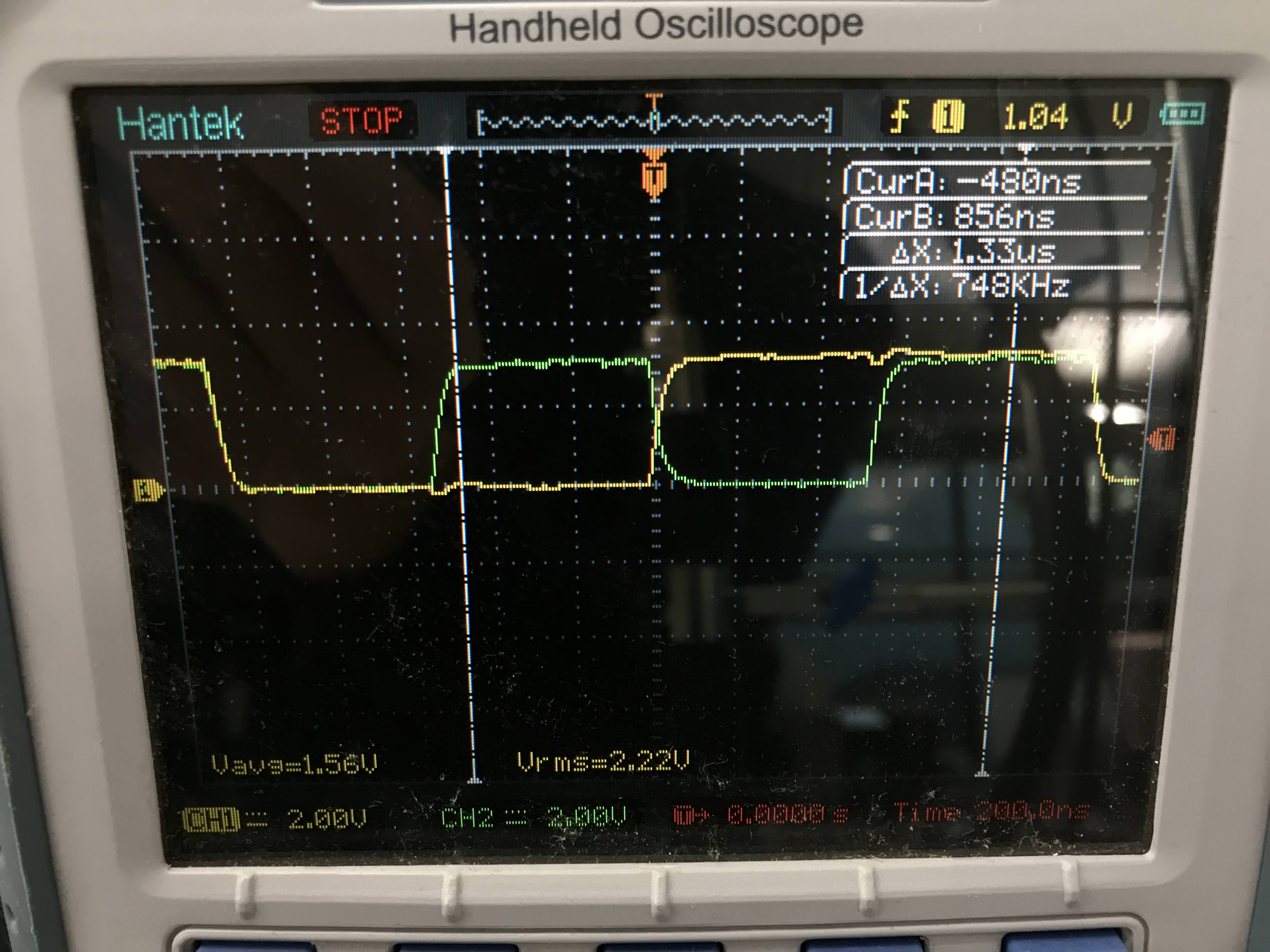
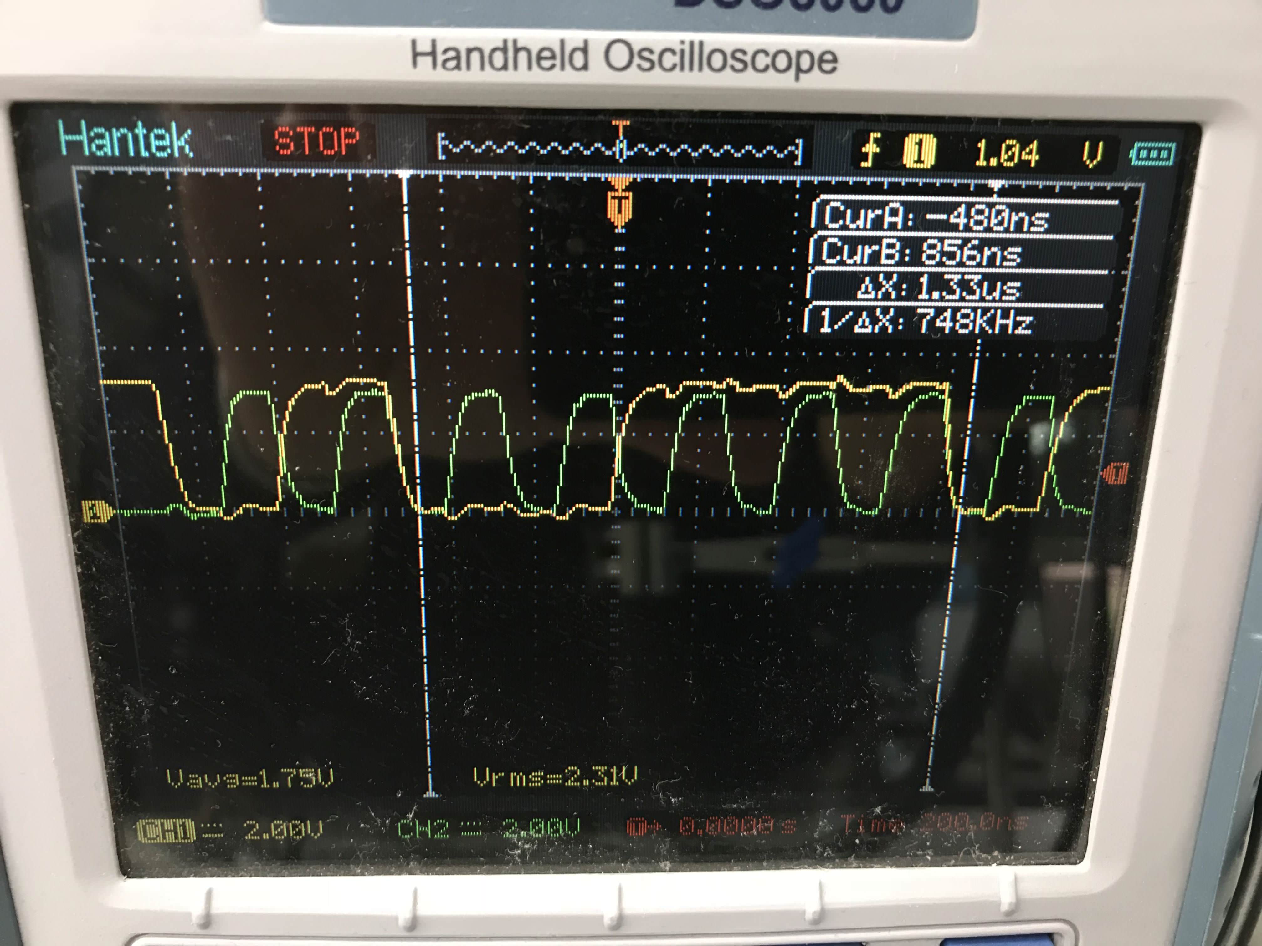
I’m assuming there’s some SPI issue, but not sure where to start debugging. Has anyone come across a similar problem before?
 
Now that I think about it, I’ve come across a very very similar issue when dealing with the I2C library. When I talk to my pressure sensors, the I2C bus, the Teensy receives corrupt data very often rendering the sensors unusable. By lowering the clock speed of the I2C bus it helped immensely (down to 100kHz from I2C FAST 400kHz).

I tried lowering the SPI clock speed down to 1MHz from 4MHz to see how it would talk to the Bluefruit, and now the Bluefruit responds reliably with no error. Problem seems to be completely gone.

I don't have a logic analyser but here's the SPI signal under an oscilloscope. This is it at 1MHz.

LFycPbp.jpg


And at 4MHz. Still seems fine? Can't see it going beyond 4MHz with those rise/fall times, but should be okay with this? It also fails at 2MHz, which should also be alright.
tXyDo8Z.jpg


I don’t understand why it's failing to accurately read this. My sensors and the Bluefruit work fine on the Arduino Nano at 4x clock speeds. Why would the Teensy suffer at typical I2C and SPI clock speeds? I’ve tried this across two Teensy 3.6’s and the issue remains. Could I perhaps have units from a bad batch of chips with faulty clocks?
 
how long are your lines? are you using terminating resistors to prevent "ringing" effect?

I've got pull-ups/downs on the I2C bus but not on the SPI. I was under the impression SPI doesn't need it? Lines are around 20cm long - they're jumper cables on a breadboard. It's the same setup I'm using on the Teensy and the Arduino.
 
its recommended to put a pullup on the CS line of SPI devices, else they'd toggle randomly, like port expanders on spi bus for example (when the mcu is reset or disconnected, CS floats.. keep it deasserted with a pullup

doesnt the nano run at 5v? perhaps your spi device worked better at that voltage
or you could lookup drive strength on teensy, if that helps, and make sure your spi device is 3.3v if your using teensy 3.6
 
Last edited:
Just tried a pulled-up CS but got no improvements.

The product page says it's regulated to 3v3 on the breakout board, so I would assume that it shouldn't make too much of a difference?

Given that I'm also having the same issues with the I2C bus, wouldn't the two issues be linked somehow? I'm using the i2c_t3 library and have to dial the I2C bus down from 400kHz to 100kHz or sometimes 200kHz to make it work as expected.
 
72MHz works well. 192MHz always seems to return this:

Code:
Adafruit Bluefruit Command <-> Data Mode Example
------------------------------------------------
Initialising the Bluefruit LE module: OK!
Performing a factory reset: 
AT+FACTORYRESET

<- OK
ATE=0

<- ��
Requesting Bluefruit info:
----------------
��
----------------
Please use Adafruit Bluefruit LE app to connect in UART mode
Then Enter characters to send to Bluefruit

I wonder if it's some clock scaling issue?
 
Playing with the clocks is why I picked those two values - tests that the hardware can work on Teensy as connected and altering the speed and math to get the specified speed - try the 3*72 value of 216. Surprised if that works - it may just be some device sensitivity to higher speed response of the Teensy that the nano would never get near - but if it's just the math . . .

Other devices have worked without such issues. I ran an I2c onehorse bubble display device on Beta T_3.6 hardware over 20 MHz - and an SSD_1306 faster than expected with no problems and the SPI bus to ILI9341 goes full speed often for display and touch.

Are these the only devices on the i2c and SPI bus respectively? What ohm pullups do you have on the i2c? If SPI is a single device then pullups aren't an issue AFAIK.
 
Same issue with the 216MHz overclock. So I guess others have had no problems with the I2C and SPI on the Teensy. I could try ordering 2 more in and seeing if that solves it. I'll order straight from PJRC this time round, hopefully to get a different batch. Could you see it being any other issue?

Yeah, at time of testing I'm running them as the sole devices on the busses. I've got 10k pull-ups on I2C.
 
Very informative link. I had 4.7k on the I2C bus when I was still having the issues and switched to 10k for some reason. I tried again with 4.7k but still didn't resolve the issues.
 
Okay so after closer inspection on the scope it seems that the SPI clock isn't delivering what it's meant to. Check out this album showing the scope measurements for the clock frequency comparing the Arduino to the Teensy.

Software SettingArduino SPI ClockTeensy SPI Clock
4MHz4MHz3.75MHz
2MHz2MHz1.87MHz
1MHz1MHz0.938MHz

It's always around ~6.6% less than what it should be. I guess that at 1MHz it's within the margin of error for the slave chip to behave correctly?

Is there an easy way to check the clock of the Teensy on some pin? If the Teensy clock is running at ~6.6% less than 180MHz, could the problem be with the clock of the uC?
 
Is there any solder resin or splatter anywhere?

Since you have a scope something simple like this might show you something if the clock is off:

Code:
elapsedMicros foo;
bool bar = 1;
#define test_pin 13
#define test_time 1000
void setup()
{
	// Serial.begin(19200);
	pinMode(test_pin, OUTPUT);
	foo = 0;
}

void loop()
{
	if (foo >= test_time)
	{
		digitalWriteFast(test_pin, bar);
		foo -= test_time;
		if (bar)
			bar = 0;
		else
			bar = 1;
	}
}
 
Okay so after closer inspection on the scope it seems that the SPI clock isn't delivering what it's meant to. Check out this album showing the scope measurements for the clock frequency comparing the Arduino to the Teensy.

Software SettingArduino SPI ClockTeensy SPI Clock
4MHz4MHz3.75MHz
2MHz2MHz1.87MHz
1MHz1MHz0.938MHz

It's always around ~6.6% less than what it should be. I guess that at 1MHz it's within the margin of error for the slave chip to behave correctly?

Is there an easy way to check the clock of the Teensy on some pin? If the Teensy clock is running at ~6.6% less than 180MHz, could the problem be with the clock of the uC?

The SPI slave should be good with the master clock unless it is too fast (out of spec for SPI device). Sometimes requested frequency is off because of discretization error -- can't get an exact frequency match from the fixed prescalers and such in the Teenys SPI hardware. However, teensy's SPI lib has an incomplete table for doing frequency calculations (github issue filed 12/1/16) and discussed at
https://forum.pjrc.com/threads/40394-SPI-clock-not-uniform?p=125745&viewfull=1#post125745
So you can actually get 4mhz from T3.6 @180mhz , CTAR0 set to 0xb8020002 instead of 0x38002003
@180mhz (bus 60mhz, spi clock max 30mhz), the best you can do for 1 mhz is 0.9375 mhz
 
Last edited:
defragster, the Teensy nails those frequencies. Tried manitou's suggestion next. It was exactly the problem with the SPI clock scaling.

Despite setting the bus at 4MHz, it still fails to read properly at an even worse rate. I mean you're right, it shouldn't matter what the SPI clock speed is at as long as it does not exceed the spec of the slave device. I'm just at a loss as to where to look next. Any more ideas?
 
on the T3.6 are you powering the Bluefruit with 3v3 on Vin? T3.6 is not 5v tolerant. if your I2C pullups were to 5v, the T3.6 may be damaged.
 
traffic is prolly too fast to see the 5v from miso, however, for sure i hope he puts pullups local to the mcu and not on the device itself
 
Status
Not open for further replies.
Back
Top