Second DAC output from Teensy 3.2

Status
Not open for further replies.
Hi all,
here we go, my first post on this board.
I'm working on a marine tilt compensated rate compass project. So far, so good, but I need to output sine/cosine analog signal for heading reference of an older radar and autopilot.
Initially I started with Teensy 3.2 and got the compass code, as well the output in NMEA2000 (sinilar to CAN bus) and NMEA0183 protocols (RS232) working. Then due to only one DAC port availability on the Teensy 3.2, I ordered nice little board called Butterfly. Unfortunately this board is kind of new and missing the low-level library for it's CAN bus, so I couldn't make the NMEA2000 libraries working. So I'm back to Teensy now. it all works well, I can output everything except second analog signal for the cosine of the heading. I know that the specs says one DAC output, but while diggin' in analog.c https://github.com/PaulStoffregen/cores/blob/392c93cb87548d6ed90d3df2affa4963cbbbbe09/teensy3/analog.c file on teensy github, I noticed that there are two functions:
void analogWriteDAC0
void analogWriteDAC1
So I decided I should ask... one never know there might be some controller pins that didn't get routed to output. I was wondering if there is a second DAC on the chip and i can modify the schematic to pull the second DAC port out (of course if it exists). This will make my DAC (oops day) and my life much easier...
Can anyone help please?
 
Just found the answer on page 106 of the MK20DX256 manual:
****************
3.7.3.1
12-bit DAC Overview
This device contains one 12-bit digital-to-analog converter (DAC) with programmable
reference generator output. The DAC includes a FIFO for DMA support.
****************
so I guess I'm out of luck on this one, unless some one has a different idea...
 
Check the manual on the K66 and K64 and perhaps buy a Teensy 3.6 - or 3.5 - they have the twin: DAC0 and DAC1. The T_3.5 would be worth the small price for upgraded RAM and SD card -maybe FPU will help and larger FLASH too - and still 5V tolerant on Digital pins like T_3.2 - and a spare CAN bus - if you use that hardware in your endeavor. T_3.6 adds a bit more to most of that as well - but becomes 3.3V only.
 
Check the manual on the K66 and K64 and perhaps buy a Teensy 3.6 - or 3.5 - they have the twin: DAC0 and DAC1. The T_3.5 would be worth the small price for upgraded RAM and SD card -maybe FPU will help and larger FLASH too - and still 5V tolerant on Digital pins like T_3.2 - and a spare CAN bus - if you use that hardware in your endeavor. T_3.6 adds a bit more to most of that as well - but becomes 3.3V only.

Thank you for the reply. I did place an order for Teensy 3.5. I think it will work great!
 
Thank you for the reply. I did place an order for Teensy 3.5. I think it will work great!

Hopefully you ordered more than one - having more than one on hand keeps them feeling replaceable ;) If you got close with the T_3.2, the T_3.5 should get you the rest of the way. It will be faster at SPEC speeds - especially if you make use of single precision floating point math. The increase in RAM and FLASH will keep you from being limited and the faster embedded SDIO socket may come in handy as well - and as long as the extra inch doesn't get in the way you'll have some easy to access extra I/O points and bus functions as well.
 
You could also use an external DAC such as the inexpensive MCP4725. It connects through I2C, has update rates up to 200kHz, 12bit rail-to-rail output and decent library support.
 
Is this a resolver output? If so do you need a reference signal as well (3 channels) or are you syncing the DAC out with an existing 400hz supply?
 
If lower quality is ok, you could use the PWM output with a low-pass filter circuit.
I don't think that will work as i have no idea of the input impedance. Or it might works, but as I don't have reliable data of what this input requires, I opted for DAC and buffered with OP AMP, so I can do an offset and gain with trim-pots. The boat is in Mexico, and I'm in Canada, so I want to get everything prepared here and take it down south with me when I go. It is hard to impossible to easy ship parts there, so I would like to be as prepared as I can.


Is this a resolver output? If so do you need a reference signal as well (3 channels) or are you syncing the DAC out with an existing 400hz supply?
I'm not sure. I know that the spec of the interface should be something I know, but i don't 100%. It is hard to fine data about it. I did many searches. the Autopilot is Comnav1001. I called them and the tech support was going to investigate and send me an email, but i still haven't received one. The Radar is Furuno 1942. Same thing, I called tech support and they didn't quite know, so they said "we are going to get back to you"...
the closes thing to specification I found here:http://www.comnavmarine.com/manuals/29030044_v1r0_Sine-Cosine_Interface_Box_Wiring_Instructions.pdfhttp:// See page 3 and page 4. It does call reference voltage and sine/cosine output
the reference voltage on this specific box can be set to
1.0;
1.6V;
2.5V;
3.4V;
4.0V;

Sine/cosine signals could be set to from
+/-0.9V to +/-1.7V in 0.1v increments then
+/-2.0V,
then the default +/-2.5V (I think this is one I need);
+/-3.1V and last +/-4.0V.
I'm not sure what ref voltage I need but somehow I shuold be able to replicate the range of reference voltages that the above box output.
I think it might be called "syncro", but I'm not certain. I'm not quite sure of where 400Hz comes into play, I'm missing something? I would like to know what were your thought on that.
 
Looks like that's what I've met as a resolver
https://en.wikipedia.org/wiki/Resolver_(electrical)
a close relative but not identical to syncros
https://en.wikipedia.org/wiki/Synchro
If that pages aren't making sense I normally describe them as a transformer with a moveable secondary. When in line you get maximal coupling, rotated 90 degrees the induced voltages cancel and you get zero and rotated further the phase of the induced signal is reversed.

Still not quite clear on the wiring but what I think happened with the original design is that the autopilot provided a AC reference (most likely 400hz, might have been 60) to an electromechanical compass within which that reference energised a resolver on the common shaft producing the sin and cos signals representing the angle. Possibly with a times 36 fine output as well for higher precision.

Anyway what the linked device does is take NMEA data and a reference not clear if you need to make this and send it to autopilot, or if it sends it to you but regardless both ends need the same one. This reference will need to be AC, in this case either 60 or 400 hz will probably work. Your sine and cos signals will be AC signals in phase (or 180 out) with the amplitude representing the sine and cos angular values of the NMEA heading.

If this is looking complex then it is, have looked at using a teensy to produce these varying signals before and given up as quite complex. Certainly not impossible but really not something I'd be flying to a ship blind with. If time is tight the solution may be two ganged Teensies, synced together from the reference. The PWM solution could be made to work but would really need access to the hardware to allow tweaking of your filter/buffer process to get an output 'good enough' for what is almost certainly a pretty basic A/D inside the autpilot which may accept a something as basic as a square wave as long as it's synced to the reference right.
 
Last edited:
Looks like that's what I've met as a resolver
https://en.wikipedia.org/wiki/Resolver_(electrical)
a close relative but not identical to syncros
https://en.wikipedia.org/wiki/Synchro
If that pages aren't making sense I normally describe them as a transformer with a moveable secondary. When in line you get maximal coupling, rotated 90 degrees the induced voltages cancel and you get zero and rotated further the phase of the induced signal is reversed.

Still not quite clear on the wiring but what I think happened with the original design is that the autopilot provided a AC reference (most likely 400hz, might have been 60) to an electromechanical compass within which that reference energised a resolver on the common shaft producing the sin and cos signals representing the angle. Possibly with a times 36 fine output as well for higher precision.

Anyway what the linked device does is take NMEA data and a reference not clear if you need to make this and send it to autopilot, or if it sends it to you but regardless both ends need the same one. This reference will need to be AC, in this case either 60 or 400 hz will probably work. Your sine and cos signals will be AC signals in phase (or 180 out) with the amplitude representing the sine and cos angular values of the NMEA heading.

If this is looking complex then it is, have looked at using a teensy to produce these varying signals before and given up as quite complex. Certainly not impossible but really not something I'd be flying to a ship blind with. If time is tight the solution may be two ganged Teensies, synced together from the reference. The PWM solution could be made to work but would really need access to the hardware to allow tweaking of your filter/buffer process to get an output 'good enough' for what is almost certainly a pretty basic A/D inside the autpilot which may accept a something as basic as a square wave as long as it's synced to the reference right.

Thanks for the detailed explanation. I had completely different impression... I thought that at any magnetic degree representation of the heading - lets say 60deg for example, my device should output 86.6025403784439% (sin60) of the swing "V" required (let's say =/-2.5V) or 2.165063509461097V and 50% of 2.5V (cos60) or 1.25V, accompanied by DC reference signal to help measure these other 2 signals accurately. So if the boat is keeping heading of 60 deg, these voltages will stay steady, and if the heading changes, they will change too respectively. The APilot can calculate the heading angle based on the two voltages.
What do you think of my theory?

I could be completely wrong here... I don't pretend I know, but this was my impression till today. I need to do some more phone calls and force them to give me the specs :)
I should not be guessing here, as it could be way more complex than I thought at first
I will report as I find out more....
 
The proof is in the advice they give, but the marine systems I work with (admittedly a very small set) use 400hz 26V resolver data to move angles between systems, so an emulator needs to be a pair of synchronous 400hz waveform generators capable of in phase and 180 phase signals (so using DAC to control an op amp gain doesn't work either since you need inversion).

It may be that this device is descended from those that used AC resolvers and used a peak detect circuit to ADC that AC waveform, and now skip the middle man and just use pure DC. Would explain some oddities in that description and greatly simplify your design.

One place to get answers may be to find out from the ship (or one closer to you with similar hardware) has DC or AC on that reference terminal, though depends of course on what is driving this project.

If you are doing marine nav system work do watch out for 115V 400hz synchro's since the signals can show up on all sorts of plugs and connectors that we would assume are safe to handle or test in these days of digital.
 
Looking at some of the other install instructions looks like your understanding is correct and they are after a DC level, though question is if the reference voltage is the peak, or the middle. Does mean PWM + driver will probably get a stable enough result.
 
Thanks everyone for the help. It is not over yet... :)

Looking at some of the other install instructions looks like your understanding is correct and they are after a DC level, though question is if the reference voltage is the peak, or the middle. Does mean PWM + driver will probably get a stable enough result.

I spoke with support guy at Comnav today and he confirmed that it is +/-2.5V swing centering on 2.5V. So the range will be from 0-5V DC
and the reference voltage is 2.5V as well. He was very rude, and I had to pry the information out of him to the point where he hang up on me...but i think I got what I needed. He did not want to email me anything.

How big of secret is that - issue of national security???

i also open a question with Furuno tech support to find out what they are going to tell me. I expect their respond from them in day or two.
In a mean time, I'm thinking of using the Teensy 3.5 with additional DAC MCP4725 the additional DAC will be to set the reference voltage level.

I will post the DAC/OP-AMP portion of my schematic once I'm done so I can get some feedback on the design from people like you that have more experience than me.
 
Looking at a wind speed sensor wiring on their manuals page, they were producing the ref level with a simple 1k+1k voltage divider. In your case with digital control of the levels you can probably just use a fixed divider from the 5V supply, or possibly a pot if you want to allow a bit of tweakage in hardware. Given the planned install location fixed resistors would be more reliable.

And yes getting answers out of people can be tedious, especially for obsolete products when they would really rather you throw the whole lot out and buy the latest from them. I'm impressed that you did actually find somebody who both knew the answer and was prepared to talk about it at all.
 
I've been digging deeper and found KVH C100 compass manual. it states the following:
***************
Two forms of analog outputs are provided: sine/cosine/reference and linear.
The sine, cosine, and reference outputs enable the user to make a ratiometric measurement of
heading data.
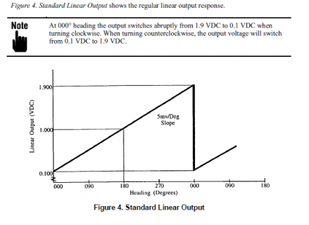
The linear output provides a 0.1 to 1.9V linear output (corresponding to 0 to 360°) with a slope
of 5mv/° and a resolution of 4mv (.8°).
The linear output with hysteresis is a variation of the standard linear output but will not shift
abruptly from 1.9V to 0.1V around the 000° heading. Figure 5. Linear Output with Hysteresis,
page 17, shows a graphic explanation.

Sine/cosine/reference outputs require a three wire interconnection with the host system. The
reference voltage stays constant at +1.50 VDC regardless of the compass heading. The sine and
cosine outputs vary ±1.0 VDC around the reference voltage (i.e. from +0.5 to +2.50 VDC).

• P2-3 (orange wire) is the sine output.
• P2-2 (red wire) is the cosine output.
• P2-1 (brown wire) is the reference output.
The sine and cosine outputs vary as a function of compass heading. To reduce error possibility,
these voltages should be measured with respect to the reference voltage and not with respect to
ground. This avoids the ground loop problems associated with single ended measurement
methods used with the linear outputs. The heading is resolved by taking the arc tangent of the
sine voltage divided by the cosine voltage. This results in a ratiometric determination of heading
having an accuracy of ±0.5° RMS.

If the user's equipment can only make unbalanced measurements (i.e. sine to ground) he should
measure all three voltages with respect to ground (i.e. sin/cos/ref). Algebraically subtracting the
measured reference voltage from both the sine and cosine voltages will result in a differential
measurement which can be used to calculate the heading as previously described.
Standard linear output.png
********
I think this explains the principal of the measurement well and I can design to that, just with the capability to vary the swing for the sine/cosine signals and vary the reference voltage to adjust for input requirement of differed devices
cheers!
 
Status
Not open for further replies.
Back
Top