Hi
I've used Teensys for several project but this is my first time in the forum. Hope I can get an answer to this problem which has me stumped.
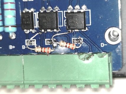
I'm trying to run a stepper motor using AccelStepper and a DIV268N driver and have it happily running as it should through an Arduino but not with a Teensy 3.1.
I am running a modification the ConstantSpeed example sketch.
This code does what it should when run on an Arduino Uno, rotating the motor at 60 rpm. But when run on the Teensy 3.1 I get no movement.
Here's the wiring setup:
PULSE+ from Driver --> Pin 13, DIR+ --> Pin 12, PULSE- and DIR- --> GND. All other pins are not connected.
I have confirmed that pin 13 isn't dead and have tried other pins anyway.
If I touch the PULSE+ wire to the 3.3V Teensy pin I can get the motor to move erratically as expected. Same if I touch to 3.3V or 5V from my breadboard power supply.
But when I touch the PULSE+ wire to pin 11 which I have set to HIGH I get no movement with the Teensy but it moves with the Arduino.
My thinking is that perhaps the current from the Teensy digital pins is inadequate to trigger the 4N25 optocouplers in the driver. I had a look at the datasheet for these but my electronics knowledge isn't up to working out what it all means!
Any thoughts on what the problem might be would be appreciated.
Thanks.
I've used Teensys for several project but this is my first time in the forum. Hope I can get an answer to this problem which has me stumped.
I'm trying to run a stepper motor using AccelStepper and a DIV268N driver and have it happily running as it should through an Arduino but not with a Teensy 3.1.
I am running a modification the ConstantSpeed example sketch.
Code:
// ConstantSpeed.pde
// -*- mode: C++ -*-
//
// Shows how to run AccelStepper in the simplest,
// fixed speed mode with no accelerations
/// \author  Mike McCauley (mikem@airspayce.com)
// Copyright (C) 2009 Mike McCauley
// $Id: ConstantSpeed.pde,v 1.1 2011/01/05 01:51:01 mikem Exp mikem $

#include <AccelStepper.h>

// HY-DIV268N-5A driver
AccelStepper stepper(1,13,12);

void setup()
{
   stepper.setMaxSpeed(1000);
   // 7.5 degree steppper motor = 48 steps/turn,
   // driver set to 1/8 step so should turn 1 rev/second
   stepper.setSpeed(48*8);
   // Increase pulse width
   stepper.setMinPulseWidth(100);
   // Set another pin high to see if it can move the motor
   pinMode(11,OUTPUT);
   digitalWrite(11,HIGH);
}

void loop()
{
   stepper.runSpeed();
}
This code does what it should when run on an Arduino Uno, rotating the motor at 60 rpm. But when run on the Teensy 3.1 I get no movement.
Here's the wiring setup:
PULSE+ from Driver --> Pin 13, DIR+ --> Pin 12, PULSE- and DIR- --> GND. All other pins are not connected.
I have confirmed that pin 13 isn't dead and have tried other pins anyway.
If I touch the PULSE+ wire to the 3.3V Teensy pin I can get the motor to move erratically as expected. Same if I touch to 3.3V or 5V from my breadboard power supply.
But when I touch the PULSE+ wire to pin 11 which I have set to HIGH I get no movement with the Teensy but it moves with the Arduino.
My thinking is that perhaps the current from the Teensy digital pins is inadequate to trigger the 4N25 optocouplers in the driver. I had a look at the datasheet for these but my electronics knowledge isn't up to working out what it all means!
Any thoughts on what the problem might be would be appreciated.
Thanks.


