T3.2 with FFT improves performance of cheap doppler radar

Status
Not open for further replies.

JBeale

Well-known member
Here's a use of the audio library for a non-audio purpose.

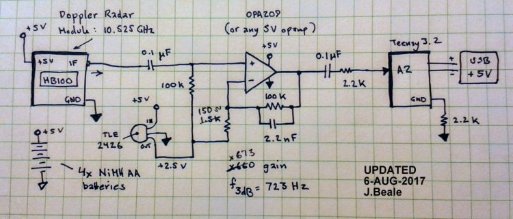
You can buy a HB100 doppler radar module for well under $5 at the usual auction sites. This sort of thing is used for automatic door openers with short range, say 10 feet. The HB100 has a mV-level baseband IF output, which I boost with a x660 opamp circuit (OPA209A) and 0.1 uF cap directly into the Teensy 3.2 pin 16 (A2). The output is a frequency proportional to target speed: Frequency (Hz) / 31.37 = Speed (mph). I use the audio library's FFT1024 object to select out just my walking speed which is 2.2 mph, which means a signal near f=70 Hz. That, plus a crude aluminum-foil-and-cardstock horn for directivity, allows a pedestrian-detection range of 80 feet, which is a considerable improvement over the "stock" sensor (esp. given radar signals drop as 1/r^4). Many thanks to Frank B for the code to cut the ADC sample rate x4 for smaller frequency bins, and neutronned for the example code I modified.

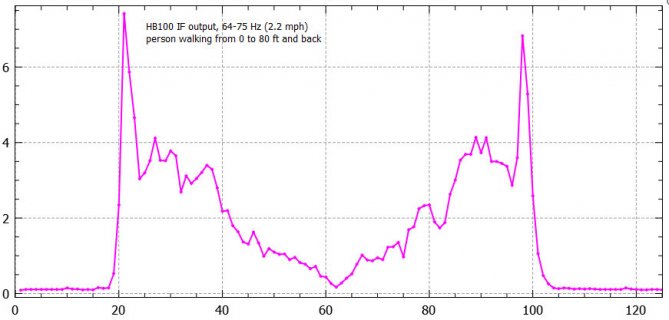
The plot below shows the 2.2 mph frequency channel as I walk directly away from the sensor out to 80 feet, then immediately return the same way.
HB100-Walking.jpg

HB100-horn.jpg

Code:
// FFT to select freq. bins from signal on Teensy 3.2 pin A2 (ADC input)
// Set OUT_ALARM pin high if signal in some freq. bins over threshold
// Thanks to Teensy forum users: neutronned and Frank B.

#include <Audio.h>

AudioInputAnalog         adc1;       
AudioAnalyzeFFT1024      myFFT;
AudioConnection  patchCord1(adc1, myFFT);

#define A_GAIN (5.0)    // gain applied to analog input signal
#define THRESH (0.5)    // threshold above which "movement" detected  
#define LED1 (13)       // onboard signal LED
#define OUT_ALARM (3)   // alarm signal (motion detected)
#define CPRINT (12)      // frequency bins (columns) to print

float level[16];  // frequency bins
float alarm;
static float fa = 0.10;  // smoothing fraction for low-pass filter
int loops = 0;   // how many times through loop
boolean motion = false;  // if motion detected

void setDACFreq(int freq) {  // change sampling rate of internal ADC and DAC
const unsigned config = PDB_SC_TRGSEL(15) | PDB_SC_PDBEN | PDB_SC_CONT | PDB_SC_PDBIE | PDB_SC_DMAEN;
    PDB0_SC = 0; //<--add this line
    PDB0_IDLY = 1;
    PDB0_MOD = round((float)F_BUS / freq ) - 1;    
    PDB0_SC = config | PDB_SC_LDOK;
    PDB0_SC = config | PDB_SC_SWTRIG;
    PDB0_CH0C1 = 0x0101;    
}

void setup() {
  AudioMemory(12);
  AudioNoInterrupts();
  setDACFreq(11025);
  myFFT.windowFunction(AudioWindowHanning1024);
  AudioInterrupts();
  
  Serial.begin(115200);
  digitalWrite(LED1, false);
  pinMode(LED1, OUTPUT);
  digitalWrite(OUT_ALARM, false);
  pinMode(OUT_ALARM, OUTPUT);
  digitalWrite(LED1, true);
  digitalWrite(OUT_ALARM, true);
  delay(1000);

  Serial.print("min");
  Serial.print(",");
  Serial.print("alm");
  for (int i=0; i<CPRINT; i++) {  // print column headers
      Serial.print(",");
      Serial.print("f");
      Serial.print(i);
  }
  Serial.println();
  Serial.println("# Doppler Microwave FFT on Teensy 3.1  5-AUG-2017");
  digitalWrite(LED1, false);  digitalWrite(OUT_ALARM, false);
  
} // end setup()

void loop() {
  if (myFFT.available()) {
    level[0] = ((1.0-fa)*level[0]) + fa * myFFT.read(0) * 0.5 * A_GAIN;
    level[1] =  ((1.0-fa)*level[1]) + fa * myFFT.read(1) * 1.5 * A_GAIN;
    level[2] =  ((1.0-fa)*level[2]) + fa * myFFT.read(2) * 2 * A_GAIN;
    level[3] =  ((1.0-fa)*level[3]) + fa * myFFT.read(3) * 3.5 * A_GAIN;
    level[4] =  ((1.0-fa)*level[4]) + fa * myFFT.read(4, 5) * 5 * A_GAIN;
    level[5] =  ((1.0-fa)*level[5]) + fa * myFFT.read(6, 8) * 7 * A_GAIN;
    level[6] =  ((1.0-fa)*level[6]) + fa * myFFT.read(9, 13) * 9 * A_GAIN;
    level[7] =  ((1.0-fa)*level[7]) + fa * myFFT.read(14, 22) * 11.0 * A_GAIN;
    level[8] =  ((1.0-fa)*level[8]) + fa * myFFT.read(23, 40) * 15 * A_GAIN;
    level[9] =  ((1.0-fa)*level[9]) + fa * myFFT.read(41, 66) * 15 * A_GAIN;
    level[10] = ((1.0-fa)*level[10]) + fa * myFFT.read(67, 93) * 18 * A_GAIN;
    level[11] = ((1.0-fa)*level[11]) + fa * myFFT.read(94, 131) * 10 * A_GAIN;
    alarm =  level[1] + level[2] + (2*level[3]) + (2*level[4]);

    if (alarm > THRESH) {
      motion = true;
      digitalWrite(OUT_ALARM, true);
    } else {
      motion = false;
      digitalWrite(OUT_ALARM, false);
    }
    
    if ( ((loops++)%10 == 0) ) {
     Serial.print((float)millis()/60000.0);
     Serial.print(",");
     Serial.print(alarm);    
     for (int i=0; i<CPRINT; i++) {
      Serial.print(",");
      Serial.print(level[i]);
     }
     Serial.println();
    }
  }
} // end main loop()
 
opamp preamp circuit for HB100

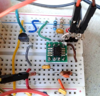
Hi Frank, the circuit I used is shown below. You can use any opamp you like. I chose the OPA209A as it works on +5V and is low noise, although comes in SO-8 so I had to use an adaptor for my solderless breadboard. I am running the HB100 + opamp on a separate 4xAA NiMH "5V" supply to reduce noise. The Teensy runs off a noisy USB +5V and you see there is a 2.2k resistor connecting the circuit grounds. I found that if I connect the USB ground direct to the opamp ground I saw much more noise. This is just a quick prototype and I need to think about how to make one +5V power supply clean enough for both circuits.

I used the TI TLE2426 3-terminal "rail splitter" device just to generate the +2.5V common from the +5V supply. You could also do this with resistors etc.

EDIT: Schematic not quite right; I first tried a gain of 67.7, but then changed the 1.5k to 150 ohms for a gain of 673.

EDIT2: I added an actual-size PDF View attachment Horn-118x90.pdf of the horn antenna pattern that I used (occupies a full 8.5x11 sheet of paper.) I folded and taped cardstock, then put Al foil on the outside and wrapped fully around the back. This is a truncated pyramid with 118 x 90 mm open end, and just fitting the 45x37 mm HB100 PCB on the smaller end. The angles and dimensions of the horn aren't critical. You don't really need it at all, but if you use a high opamp gain for longer range as I did, without some kind of reflector you'll get a lot of pick up of motion to the side and behind the sensor as well as in front.

For example, one location I had in mind was on the front porch, to detect people coming up the walkway. In that case you don't want it to trigger on people moving inside. I found the microwave signal does go right through a wood door unless there's some kind of reflector behind it.

Updated-Preamp-Circuit.jpg20170806_103458.jpg
 
Last edited:
I'm going from memory but isn't the gain for a non-inverting op-amp 1 + Rf / Rin = 1 + 100K / 1.5K = 67.66. Can someone check my math??

I like that little virtual ground part!! Gotta play with that!

Great project!!
 
Your formula is quite right. I actually had two versions of the project, and I confused them. At first I used 1.5k as Rin but decided I could do better with more gain, so boosted the gain 10x with Rin = 150 ohms. So the gain is (about) right, but I mislabeled the resistor. I edited the previous post to show the corrected schematic.

NOTE
to anyone trying this out: I also added the PDF of the horn antenna I made. If you don't add something like this, you'll get a fair amount of pickup off the back side of the device, not just the front.
 
Last edited:
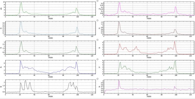
addendum: plots of other frequency bands

By the way: given the radar range equation says return signal should go as 1/r^4, you may question why my plot looks more linear with distance. I'm wondering that too. If you look at the other frequency bands they are each different, but mostly tend toward a much steeper-than-linear falloff with distance. The upper-left plot "alm" is a linear combination of the first four frequency bins. Might be fun to make an algorithm to look at all the channels, and try to optimize SNR for detecting pedestrians at various distances, cars etc.

FFT-bands-walking.jpg
 
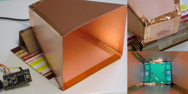
horn made out of PCB laminate sheets

Made a new horn antenna from thin FR4 copper-clad. Was able to tape up the back with copper foil more tightly and the whole assembly is more rigid, so this one doesn't detect a hand waving right behind it, where the aluminum-foil version would. Otherwise performs about the same in the forward direction. Aesthetically looks better I think. The HB100 board is just taped with a few pieces of copper tape flat against the bottom inside the horn.

HB100-horn-T32.jpg
 
Last edited:
JBeale. Nice job congratulations. Any guidelines on designing the horn?

Here's the horn I made: View attachment Horn-118x90.pdf however I think nothing about it is particularly critical. You can choose a different size and different opening angles, and it will still more-or-less work. That particular horn is a scaled-down version from a design I found online for amateur radio astronomy at a longer wavelength: http://www.setileague.org/articles/horn.htm

I'm no expert on horn theory. I seem to remember the far-field pattern is 20 dB down (?) at the flare angle of the horn, but then you may have any number of sidelobes nearly as large as the main lobe, depending on the horn length in wavelengths, and various other details.

Usually you have a single feed point at the apex of the horn. In this case with the HB100 board you have two separate dual patch antennas for Tx and Rx, one on each side of the board. So I wasn't sure how the horn would work with this arrangement, but it still does work.

I don't know what the exact antenna pattern is. I don't have any microwave gear besides the HB100 but I now have a few more parts on order in hopes of being able to measure the antenna pattern at least in a qualitative way.
Specifically http://www.ebay.com/itm/New-AD8317-...or-Power-Detector-for-Amplifiers/311857360564 although I then found the chip is only intended for use through 8 GHz and only "sort of" works out to 10 GHz. We'll see if 10.525 GHz works at all. Maybe the best test is just recording the response while panning the antenna across a distant spinning or vibrating metal target, I've been thinking how to set that up.
 
Last edited:
Thanks for the response. I was playing around with this module a couple of years back and had it breaded board up and then found the breakout board for it on tindie. It worked sort of... Never even dawned on me to run it through a fft. Now I have to break it out again and start fiddling with it again.

Mike
 
Here's a tip, if you want any decent range you cannot use a switching power supply, only a linear regulator or even better a battery. It basically doesn't work at all if you try to use a regular 5 volt USB supply. The super simple HB100 circuit has sub millivolt output and just about no power supply rejection, so switcher noise dooms your signal.

Also: note both HB100 and CDM324 have some DC bias on the IF output. Neither will survive accidentally connecting +5V to the output pin.
 
Last edited:
A few more photos of the ongoing project: https://goo.gl/photos/HXv2KXP9rxkUAzrAA

It is (relatively) easy to get good performance running entirely from AA batteries. Running from a noisy 12V supply (switchmode), not so easy. I tried several things while looking at the amp output on a scope. As a result, I've got a linear regulator from noisy +12 down to cleaner +5V and three separate common-mode chokes, plus various RC pi filters, and shielded stereo lav mic cable for some signals. Three separate metal cans enclose the regulator, opamp circuit, and Teensy 3.2 board respectively. No hope to use a direct USB connection from Teensy to a PC due to noise; instead I use TTL serial through a 1k resistor (TxD) and 100 ohms (GND) to further isolate things from digital hash on the PC power rails.

After doing all this, it can detect a kid walking *across* the field of view (so the radial velocity is very small) who is visible only in a small gap between parked cars over 80 feet away. However as you might expect, at that sensitivity setting you also get lots of tree & foliage movement as well.

Also, two units I tested are different, one is less sensitive than the other and about 2x more noisy. Maybe a diode partially killed by static zap? Be careful. These boards pick up nearby cellphones and wifi routers as a noise signal, as well.
 
Last edited:
spectrogram from CDM324

Here's what the 24 GHz module CDM324 (without any horn or other reflector) shows as I walk out 50 feet, stop and come back. This spectrogram was generated by Audacity on a Windows PC, sampling at 8 kHz with a 1024 element FFT, so the Teensy would have the same information using the audio lib 1024 element FFT. The trick is to analyze the data to extract "person walking" from "trees blowing in wind" and other noise. Fun how you see the arms & legs moving forward and backwards. By contrast a car is less complicated because almost all parts of it (except the wheel spokes) are moving at the same speed. There seems to be some constant broadband noise around 400 Hz.*

170904-Doppler-24G-walkBkYard-50ft.jpg

*which turns out to be an instability due to capacitive loading of a reference buffer in my preamp; since fixed.
 
Last edited:
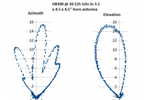
In case of interest, a measured transmitted-power antenna pattern from the HB100 sitting in the truncated pyramidal horn. Using a laughable kludged-together pile of uncalibrated gear. I was curious what the effect of the dual patch sitting at the base of the horn offset from center, would look like. The pattern is offset from the centerline as I expected; I didn't guess the horizontal lobes would be quite so pronounced though.
HB100-horn-output-pattern.png
 
another horn antenna

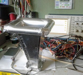
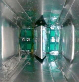
I made another horn using aluminum flashing (thin sheetmetal) and aluminum HVAC tape, with a slight exponential curve (eg. flared instead of straight) and a rounded lip which reduces edge diffraction. Looking into the horn you can see a V-shaped "nose" on the HB100 PCB itself, separating the TX and RX antenna patches. I did not measure it, but this assembly seems to have a fairly smooth pattern, without the distinct separate lobes of the simpler horn design. In theory, this horn should be about +18 dBi (but mine is surely less, as I don't have a clean single-mode feed). In practice, looking at a spectrogram of the output signal, I can distinguish the periodic stride pattern of a single person walking out to about 200 feet, if they are on-axis and moving directly towards or away from the antenna.

20170930_ExpHornOutside.jpg 20170930_HornInside.jpg
 
Last edited:
@JBeale. Finally found my HB100 modules. Ran the code on a T3.5 at 120 with fout from the backpack (it gives both fout and a vout). I did attach it to pin 2 on the T3.5 hope that still holds. Although I saw something that the t3.5 had adcs on pins a10/a11?

One thing I can confirm is that you definitely need some shielding or a horn to get better performance otherwise it picks up motion from the sides as well as from down below.

Mike
 
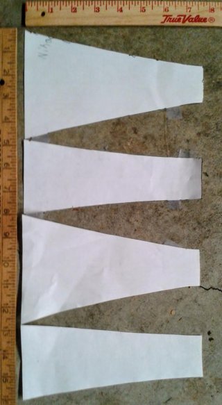
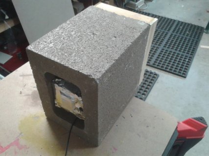
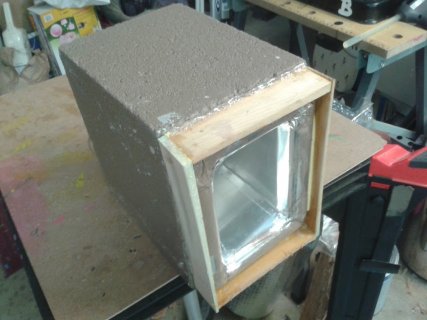
I don't have a PDF of the new curved horn. It is not dramatically curved. I just made a mockup pattern by eye out of paper (see photo), and then used that to cut it out of aluminum flashing from Home Depot (if you do this, wear gloves!). I later added tabs at both ends that (rolled over a PVC pipe as former) became the front lip, and folded over at rear for a box to hold the HB100 board. Also tabs folded over along the edge to help hold the adjacent side. It was sized to just fit (except for the curved lip) in a 3 x 5 x 7.5 inch volume, as that is the opening in the 7.5 x 7.5 x 5.75 cement block that I put it in. Finished with wood strips around the lip and .02" polystyrene sheet over the front, and all painted with the same exterior paint as the rest of the house, it doesn't stand out. Both latex paint (after drying) and polystyrene are near-transparent to microwaves.

I was thinking to use it as an automatic doorbell, detecting people coming up the walkway. Turns out it can also detect cars passing on the street about 70 feet away, even though traffic moves across the field of view with near zero radial velocity. I guess the step-change in return signal as the car appears and disappears is enough. A car makes one sharp peak and decay in the output about 1 second long, and a person walking up shows a more sustained level with the characteristic whup-whup fluctuations as their legs move, lasting 3 or more seconds. It sometimes picks up birds swooping past, as a brief <1 sec narrowband tone.

HornPattern-20171029_092412.jpg
Horn_20171001_132750.jpgHorn_20171001_132740.jpg
 
Last edited:
Status
Not open for further replies.
Back
Top