MS5611's I2C not detected on Teensy 3.6 but detected on Raspberry Pi !

Status
Not open for further replies.
Hello Everyone,

I have a MS5611 GY63 barometer. I can detect its correct i2c address (0x77) on my Raspberry Pi with i2cdetect. And the chip is fully functional with some of my barometer code.

But the teensy 3.6 can't detect it. I checked that with I2C scanner. I've connected it to the pin 18 and 19. The thing is that other sensors work on these two pins. Only MS5611 can't be detected.

What is going on here? Thanks a lot for helping!
 
You mostly likely need pull-up resistors to use i2c on Teensy. Solder one 2.2k resistor between 3.3v and pin 18. Solder a second 2.2k resistor between 3.3v and pin 19. The 2.2k resistor is a common value to use on Teensys, but if you have a complicated i2c setup, you may need different values. The other sensors probably already have pull-up resistors attached. If that is the case, then you should be able to put both devices on the i2c bus, and the device with the pull-up resistors will allow the other without the resistors to work.
 
Thanks Michael.

1. Why could the sensor be detected and run on Raspberry Pi without a pull-up resistor, while not on Teensy 3.6? What is the reason to add a pull-up resistor?

2. I tried having both MS5611 and another working sensor (BNO055) connected to i2c. Still the i2c could only find the BNO055 but no MS5611.

A more comprehensive explanation is appreciated. I am a newbie : )
 
1. Why could the sensor be detected and run on Raspberry Pi without a pull-up resistor,

Raspberry Pi has 1.8K pullup resistors.

while not on Teensy 3.6? What is the reason to add a pull-up resistor?

Teensy does not have the pullup resistors. Those pins can be used as analog inputs or other uses where resistors would interfere.

Raspberry Pi doesn't have analog inputs. Teensy does.

A more comprehensive explanation is appreciated. I am a newbie : )

You definitely do need to add the pullup resistors when using bare I2C chips or breakout boards without built-in resistors (though most from Adafruit, Sparkfun and others have the resistors).

Hopefully that's comprehensive enough?
 
Ah! I think that's easy enough for me to understand! Although I need to google a bit more on what pull-up resistor is for...Thank you both!
 
Hi....I tried placing a 2.2k resistor between SDA0 and 3.3V, and another between SCL0 and 3.3V. Now the BNO055 that used to work can't be detected. The I2C seems broken?


I used this code to scan the I2C and it shows "unknown error at 0x01"


#include <Wire.h>


void setup()
{
Wire.begin();

Serial.begin(9600);
while (!Serial); // Leonardo: wait for serial monitor
Serial.println("\nI2C Scanner");
}


void loop()
{
byte error, address;
int nDevices;

Serial.println("Scanning...");

nDevices = 0;
for(address = 1; address < 127; address++ )
{
// The i2c_scanner uses the return value of
// the Write.endTransmisstion to see if
// a device did acknowledge to the address.
Wire.beginTransmission(address);
error = Wire.endTransmission();

if (error == 0)
{
Serial.print("I2C device found at address 0x");
if (address<16)
Serial.print("0");
Serial.print(address,HEX);
Serial.println(" !");

nDevices++;
}
else if (error==4)
{
Serial.print("Unknown error at address 0x");
if (address<16)
Serial.print("0");
Serial.println(address,HEX);
}
}
if (nDevices == 0)
Serial.println("No I2C devices found\n");
else

Serial.println("done\n");

delay(5000); // wait 5 seconds for next scan
}


Need helllllllp! T_T
 
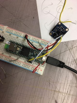
can you attach a photo of how you wired things up?

I'm not with my stuff now. But basically I just hooked the BNO055 to 3.6V, ground, SDA and SCL. That's it. It used to work but can no longer be detected now. It's after I tried connecting 3.3V and SDA, and 3.3V and SCL with a 2.2K resistor, respectively. (MS5611 was hooked to 3.3V back then and both sensors shared the same SDA and SCL)
 
20170807174342.jpg
Here it is. Just basic connection that used to work. I hope I didn't destroy teensy!!
 
That connection looks like it should work. That Adafruit board has the required resistors.

Maybe not. Looks like breakout board is being powered by Vin (5v), so that makes the pullups on the breakout board 5v, and that won't make the T3.6 I2C pins happy. T3.6 is NOT 5v tolerant.

should power from 3v3 on Teensy. may have damaged I2C pins?
 
Last edited:
Maybe not. Looks like breakout board is being powered by Vin (5v), so that makes the pullups on the breakout board to 5v, and that won't make the T3.6 I2C pins happy. T3.6 is NOT 5v tolerant.

should power from 3v3 on Teensy. may have damaged I2C pins?

That pin is 3.6-6V. I've run the sensor with this connection many times. Also I tried switching to different I2C (pin 37 and 38). Still no response.

Things changed right after I did this, according to the first reply.

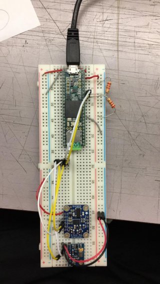
07191747.jpg


I am just being curious of the reason how adding couple resistors between SDA/SCL and 3.3V all of sudden damaged the I2C pins (maybe?)...
 
The first photo is bad for the T3.6, you are powering the BNO055 with 5v.

the 2nd photo is not good, because you have BNO055 at 5v and the MS5611 at 3.3v, and both wired to the same I2C pins, but i'm not sure what the electrical implications are of having 5v and 3.3v on the I2C pins ....

I suspect T3.6 I2C is fried. if you power BNO055 with 3v3, does I2C scan work.

"That pin is 3.6-6V." When powered from USB, the top right pin will be at 5v

EDIT: in duplicate thread, Paul notes that breadboard in 2nd photo likely has split rails, so you need to provide 3v3/gnd to the lower rails
 
Last edited:
The first photo is bad for the T3.6, you are powering the BNO055 with 5v.

the 2nd photo is not good, because you have BNO055 at 5v and the MS5611 at 3.3v, and both wired to the same I2C pins, but i'm not sure what the electrical implications are of having 5v and 3.3v on the I2C pins ....

I suspect T3.6 I2C is fried. if you power BNO055 with 3v3, does I2C scan work.

"That pin is 3.6-6V." When powered from USB, the top right pin will be at 5v

The BNO055 is now connected to the 3.3V but couldn't be found on I2C...Darnit!

Looks like I will have to order another T3.6 ... and try the pull-up resistor method again for my MS5611.

So the 2nd photo is OK if BNO055 is powered at 3.3V and pull-up resistor connected that way?
 
Can you still usably Program the T_3.6? If there was I2C damage it maybe more than just those two pins - but you could try Wire1 and pins 37/38 for SCL/SDA at 3V3 - or Wire2 on pins 3/4.
 
The BNO055 is now connected to the 3.3V but couldn't be found on I2C...Darnit!

Looks like I will have to order another T3.6 ... and try the pull-up resistor method again for my MS5611.

So the 2nd photo is OK if BNO055 is powered at 3.3V and pull-up resistor connected that way?

Note, the T3.5 is 5v tolerant, but i think hookup in photo 2 would be harmful even for T3.5.

With 3v3 and you have both BNO055 and MS5611 hooked to the I2C, you may not need the extra resistors since the Adafruit BNO055 has 10K pullups on the breakout. Try it. If you only have the MS5611 hooked to the I2C, you will need pullup resistors.

(you mentioned you had tested with pins 37/38, so Wire1 may be toast as well. As defragster suggests, Wire2 might still work, but i don't know how extensive the 5v damage may be. i'll let the EE's speculate ...)

I2C pullups reference: http://www.dsscircuits.com/index.php/articles/47-effects-of-varying-i2c-pull-up-resistors
With 2.2K pullups in parallel with 10K pullups, the effective resistance is about 2K ohms
 
Last edited:
OK....Some magic just happened.

I bought another Teensy 3.6, tried BNO055 on I2C, works. Then tried MS5611 on I2C, works.

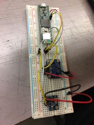
But as soon as I connect them both to the same I2C (this time I powered them with 3.3V and assumed BNO055 has internal pull-ups)...scanned the I2C...And their I2C address vanished again!!!

13173326.jpg

Same phenomenon as before.

Here is the magic.

Afterwards I tried these two sensors on Arduino Due, comparatively, scanned the I2C and found the sensors.

And then I connect each back to the Teensy3.6, including the one I thought on which I2C bus was fried. They both work!

So the I2C bus seemed not fried on the old one.

And question goes to why T3.6 couldn't recognize the sensors when they are connected at the same time.
 
Last edited:
when both are connected, do you still have the external pullup resistors connected? if not you might try both with and without external pullups. the EE's will have to comment on what would be good values for external resistors when both devices are hooked to I2C.

(attachment is unreadable)
 
I fixed the attachment. I tried with and without pull-ups. As soon as these two sensors were connected to the I2C, the T3.6 just lost their I2C address.
 
Status
Not open for further replies.
Back
Top