Converting Due specific code to general SPI library

Status
Not open for further replies.

JuanCena

Member
I am attempting to upgrade a previous project, which is using the Arduino Due to convert an analog compass to a digital one. The updated version will instead use the Teensy 3.5 and both versions are using the ADS7871 as their analog to digital converters. To do this some parts of the code had to be changed as they were using the extended Due library. These changes should be as simple as removing the pin select and SPI_CONTINUE arguments from the SPI.transfer command and replacing them with 2 digitalWrite commands first setting the chip select pin LOW before the transfer and HIGH after. However, doing this causes the output to get stuck on 45 degrees, which in binary is simply an output of all 1's.

I have tried using the SPI.begintransaction command to no success as well as a multitude of other changes. Strangely, when I change only a single, specific transfer command (the one dealing with the short "ref") from the due specific code to the general SPI library it still works perfectly. However, if I change the transfer command directly below it (the one dealing with the short "adc") which has the exact same supplemental code it breaks the code just as previously described (outputting all 1's). Attached is the code in its current state which works as designed, with the only deviation from the original code being to the single transfer command dealing with the short "ref". I have also attached 2 extremely simplified version of my code one of which uses the Due specific library and appears to work correctly and the other using the general SPI library which once again outputs all 1's.

Does anyone have any idea what could be wrong with this? I've been tearing my hair out for days trying to figure this out.
 

Attachments

  • resolver_reader_v24.ino
    28.8 KB · Views: 108
  • resolver_reader_abbreviated_Due.ino
    555 bytes · Views: 110
  • resolver_reader_abbreviated_Tennsy.ino
    620 bytes · Views: 103
You need to set pin 4 into output mode... Like:
Code:
  #include <SPI.h>
  #include <stdint.h>

void setup() {
  // put your setup code here, to run once:
  pinMode(4, OUTPUT);
  pinMode(10, OUTPUT);
  SPI.begin();
  delay(1);
  digitalWrite(4, HIGH);
  digitalWrite(10, HIGH);
  digitalWrite(4, LOW);
  SPI.transfer16(0b0000001100000100);
  SPI.transfer16(0b0000011100111100);
  digitalWrite(4, HIGH);
}

void loop() {
  // put your main code here, to run repeatedly:
  digitalWrite(4, LOW);
  SPI.transfer(0b10001000);
  int test1 = SPI.transfer(0b00000000);
  int test2 = SPI.transfer(0b00000000);
  digitalWrite(4, HIGH);
  SerialUSB.print(test1, BIN);
  SerialUSB.print(" - ");
  SerialUSB.println(test2, BIN);
}

I went ahead and tried that and continued to have the same issue with the all 1's output. I also tried adding in the SPI.beginTransaction and SPI.endTransaction commands with no success as well. I have attached the version with both new commands added. I feel like I'm doing this exactly as it should be done but the same issue persists. Any other thoughts on what it might be?
 

Attachments

  • resolver_reader_abbreviated_Tennsy.ino
    620 bytes · Views: 97
Again your ino file did not set the pin into output mode.

I did verify that your program modified to set pinmode and using SPI begin transaction does generate valid SPI
Code:
#include <SPI.h>
#include <stdint.h>
SPISettings spi_settings(4000000, MSBFIRST, SPI_MODE0);

void setup() {
  // put your setup code here, to run once:
  pinMode(4, OUTPUT);
  pinMode(10, OUTPUT);
  SPI.begin();
  pinMode(4, OUTPUT);
  pinMode(10, OUTPUT);
  delay(1);
  digitalWrite(4, HIGH);
  digitalWrite(10, HIGH);
  SPI.beginTransaction(spi_settings);

  digitalWrite(4, LOW);
  SPI.transfer16(0b0000001100000100);
  SPI.transfer16(0b0000011100111100);
  digitalWrite(4, HIGH);
  SPI.endTransaction();
}

void loop() {
  // put your main code here, to run repeatedly:
  SPI.beginTransaction(spi_settings);
  digitalWrite(4, LOW);
  SPI.transfer(0b10001000);
  int test1 = SPI.transfer(0b00000000);
  int test2 = SPI.transfer(0b00000000);
  digitalWrite(4, HIGH);
  SPI.endTransaction();
  SerialUSB.print(test1, BIN);
  SerialUSB.print(" - ");
  SerialUSB.println(test2, BIN);
  delay(250);
}
This program compiles and downloads.
screenshot.jpg
Also verified with Logic Analyzer that the data was what I expected it to be, as from your program. I did not verify if your actual commands were correct for the actual device.

Other advice, show actual picture showing your wiring. Also double check them. Things that I have run into include. Assuming that the clock pin (13) is the next pin after 12 on the board... It's not, it is on the other side of the board. Also have seen people put it into breadboard with pins not soldered in, so no electrical contact...

Another possibility. I don't use this chip, but I remember there were some conversion chips like this, that do something with one of the signal pins like the Clock to say that they are busy? Again not sure if this is one of those chips... Also I might be tempted to monitor the busy status off of the chip if you have a free IO pin... Hopefully someone who uses these chips will give some more insight
 
For the fun of it I dug out my one Arduino Due (early version)... Again I don't have your chip so can not tell how it interacts.

I ran your stripped down version of the Due program from posting #1...

I verified the same outputs on the SPI buss and pin 4 as with the Teensy.
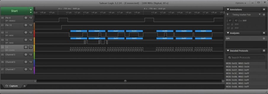
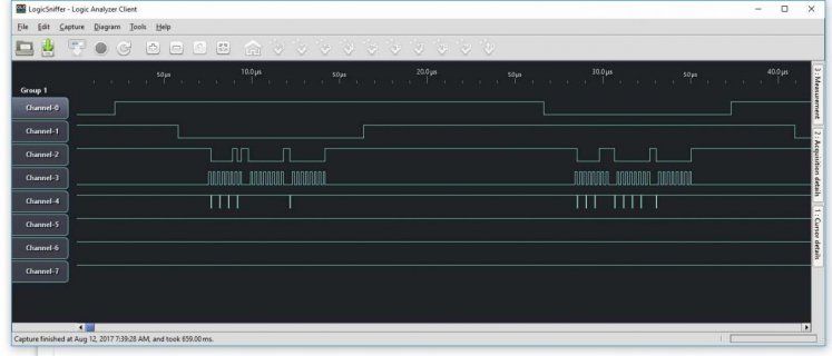
From The Teensy we have:
screenshot.jpg

Now with the Due, we see:
screenshot.jpg

Differences: With Teensy the SPI is running at about 3.7MHz where the Due is running at 4.0MHZ.
But the big difference is time between bytes. WIth the Teensy it is only about .12us whereas on DUE it is something like 1.07us or almost 10 times longer delay between bytes.

So wondering what would happen if in the above program for Teensy if you added in a small delay?
Code:
  // put your main code here, to run repeatedly:
  SPI.beginTransaction(spi_settings);
  digitalWrite(4, LOW);
  SPI.transfer(0b10001000);
  delayMicroseconds(1);
  int test1 = SPI.transfer(0b00000000);
  int test2 = SPI.transfer(0b00000000);
  digitalWrite(4, HIGH);
  SPI.endTransaction();
  SerialUSB.print(test1, BIN);
  SerialUSB.print(" - ");
  SerialUSB.println(test2, BIN);
  delay(250);
}

Might experiment with 1 or 2 Microseconds, may also need to add one between 2nd and 3rd byte as well...

But again this is assuming the wiring is correct...
 
I did set the pin mode to output. I think you might have just glanced over it because in your code it's in there twice. I did run your code as is, unfortunately with the same results.

The Logic Analyzer data is quite interesting, although it makes it even more baffling to me that it doesn't work as intended.

I can include a picture if you think it will help I'm just afraid it won't for a couple of reasons. First of all, there are a lot of wires and it is very hard to discern what is going where, and would be even harder in a picture. Secondly, because the program works perfectly using the Due specific code I don't believe this is the problem. I can verify that this code is working correctly as the compass is from an aircraft and therefore has a heading needle as well as a directional one. I can therefore adjust the heading and watch as the output on my screen changes and remains accurate to the needles poison.

That is an interesting thought, I didn't know that some chips work like that and it's definitely a possibility. I did a bit of digging and I haven't seen anything suggesting the chip works like that on the datasheet or elsewhere on the internet but both are quite expansive so I will continue searching.

I had previously messed around with the delays but I went ahead and did it again as suggested but to no avail.
 
I did set the pin mode to output.

The code you attached to msg #3 (resolver_reader_abbreviated_Tennsy.ino) definitely is missing pinMode(). Anybody can clearly see this. It's only 26 lines, and none of them has pinMode. But 6 of those lines have digitalWrite to pins 4 and 10, which will not work because pinMode() was never used to configure pins 4 and 10.

because the program works perfectly using the Due specific code I don't believe this is the problem.

I believe the Atmel SAM8X chip pin mux works similarly to the one on Teensy 3.x. The pin can be muxed between GPIO, SPI, other stuff, or completely disabled (which is the default). I'm pretty sure that special SPI.begin() on Due puts the pin mux to SPI control. The special libs like ILI9341_t3 do the same, where the chip select pin is controlled by SPI, not GPIO. But most programs just use the ordinary way of controlling the chip select pin with digitalWrite().

On Teensy 3.x (or Due), for digitalWrite to work the pin mux needs to be configured to GPIO mode. Calling pinMode(pin, OUTPUT) does that. But if the pin isn't configured for GPIO for whatever reason, lacking pinMode or other stuff has changed the mux, then digitalWrite will have no effect.
 
On some processors, and I know this is the case with AVR, the pins default to INPUT mode. On those chips, while input mode is configured, writing to the pin turns the pullup resistor on and off. Due and Teensy both have code to emulate this quirk of the AVR hardware.

So if you have code which happens to work on a non-Teensy board without using pinMode, it may actually be controlling the pin by turning the weak pullup resistor on and off, either because the AVR hardware implements it, or because code in digitalWrite is trying to emulate that AVR hardware feature.

On Teensy 3.x, the pins default to a low power disabled state. They do NOT default to input mode. This is one of the few areas were Teensy does not try to closely mimic AVR hardware, because input mode without a signal connected can lead to extra power consumption when the pin "floats" to a voltage between well defined logic levels.

Just because something happens to work on Due or other boards done not necessarily mean it is implemented correctly. This pinMode requirement is one of the very well known cases. To be a bit blunt, the attitude that the code must be ok because it works on Due together with the sample program on msg #3 lacking any pinMode doesn't paint a good picture of earnest effort. Hopefully this clearly worded message can help get the pin across that pinMode absolutely is needed on Teensy, and that code which is improperly designed but happens to work by mistake on some boards is actually pretty common in the Arduino world.
 
Note I agree with Paul, that having both versions of your test app, not setting pinMode.... Made me wonder... But I will assume you have done so now...
The Logic Analyzer data is quite interesting, although it makes it even more baffling to me that it doesn't work as intended.

I can include a picture if you think it will help I'm just afraid it won't for a couple of reasons. First of all, there are a lot of wires and it is very hard to discern what is going where, and would be even harder in a picture. Secondly, because the program works perfectly using the Due specific code I don't believe this is the problem. I can verify that this code is working correctly as the compass is from an aircraft and therefore has a heading needle as well as a directional one. I can therefore adjust the heading and watch as the output on my screen changes and remains accurate to the needles poison.
Again here is another issue. We still have no clue what exactly is hooked up to what and How?

For example is there a common ground wire, from the Teensy to the Analog chip to the GPS? Is there proper power to all of them... Maybe MISO and MOSI are hooked up backwards. Maybe the clock wire is not actually hooked up to pin 13? Maybe you have other things connected up? For example maybe you have an Audio board connected UP?

So again hard to say what is going on. Would be good if you could simply wire up Analog chip with simple POT or the like and make sure that works...

Edit: As for Logic Analyzer... Would not leave home without one! https://www.saleae.com/
Short of that, I would try to do some simple things like, use a multi-meter to check out voltages at the different boards/chips, plus check that you have continuity from Teensy SPI pins (11, 12, 13) to the appropriate pins on the analog chip.
 
Last edited:
sorry, as I mentioned I do not know this chip, But my quick look at the guide makes it sound to me, like issuing the
command byte: 0x88 says start an analog conversion single ended on LN0 and when it completes store the results in the register...

It then sounded like you might issue the command byte with the MSB bit not set and then you read an appropriate register.
Some code I saw for arduino looked like it initiated a conversion process, then it cycled reading either register 4 or 5 and check the approrate bit coming back to see if the conversion is busy or not. Once it is not busy, it would then read in registers 0 and 1 to get the converted values...

Again that is only my 5-10 minute walk through of this processor chip... Could be totally wrong.
 
I must have accidentally uploaded the old code that didn't include setting the pin mode to output. I assure you however that it is there now.

I should have been more clear but I'm not even trying to run this code on the Teensy yet. I am just changing the software to the general SPI library and trying to get it to work on the Due as I know that hardware is working correctly. Therefore, I believe that this isn't a hardware issue but at this point I don't think much would surprise me.

Kurt, it seems that what you found is someone who is sending a direct mode command and then having the result sent back via a register mode command. What we did is put the chip in read back mode using a register command and then use direct commands to get an output. If your interested, you can find detailed explanations of this on page 16 of the data sheet here:
http://www.tij.co.jp/jp/lit/ds/slas370c/slas370c.pdf
 
Last edited:
So you are still testing on Due. Again maybe it would help to see an unmodified version of your program to be able to verify what the actual data is being sent and on what pin...

Example in your current first main program it looks like the select pins are changed from 9, 10 to 4, 10?
 
Agreed, go back to the original program and put many Serial.print() into it so you can see everything transmitted and received in the Arduino Serial Monitor. Copy and paste the known good communication to a text file so you can look at it side-by-side when you run a modified copy with similar Serial.print().

And, as a general guideline, we tend to help much better when you're show us what you're really going. Don't tell, show with photos and complete code, and be honest about you're really up to. If we have a poor picture of what you're doing, we really can't help as well.
 
That is quite strange the pins should have been set back to 4 and 10. Defiantly a mistake on my part and I think that explains why when I changed just the code surrounding the "ref" value to be general SPI it appeared to still work. I went back and tested this again and while it appeared to work at first it broke once it got out of the first quadrant (between N and E). So at least we are consistently having the same problem with the general SPI usage.

Anyways, I have attached the original code. There have been some minor adjustments, just adding the buffers and changing SPI.transfer to SPI.transfer16 in the setup, both of which you can see commented out. I did just test it and it is working perfectly.
 

Attachments

  • resolver_reader_v23.ino
    28.3 KB · Views: 86
Paul, I am actually about to go home for the day but I will upload some pictures tomorrow. I also have included my complete code I just also included some simplified code because I thought it would help illustrate the problem. Also, I have been nothing but honest I don't understand why you would think anything differently. And if you don't fully understand what is going on please feel free to ask any questions you think would help clarify.
 
Note: I played with your version 23 in posting #14 and saw the Arduino DUE output on Logic Analyzer. I then edited it with #ifdef to allow you to use what I would call STANDARD_SPI else it falls back to the Arduino DUE type version. I then checked output on Logic analyzer and I think it looks the same...

The #define is first line of code. You might try it and see if it works? If not comment out the #define and see if that still works...

Forgot to mention that downloading the Saleae logic analyzer code does not do much without one of their logic analyzers... I was using one of their Pro 8 versions on this one...
 

Attachments

  • resolver_reader_v23.ino
    29.8 KB · Views: 85
Thank you that is very useful for testing, I had no idea you could do that. When running on the Due it works perfectly with that first line (#define STANDARD_SPI) commented out however, when that line is left in there it breaks as it has before, outputting only 45 degrees. This is pretty much how I expected it to work and is consistent with the problems I've been having. Interestingly however, when running on the Teensy and with that first line of code left in it breaks but this time outputting all 0's. As expected when you comment the first line out it won't compile as it doesn't understand the Due specific library.

I think the most notable information gained from this is that the code breaks differently on the Due than on the Teensy. Although, that could be due to some sort of hardware issue on the Teensy as it is untested.

Yeah, I definitely did not realize that at first. It sound like something my boss would be interested in purchasing but, with only about a week left before I go back to school I would only get maybe a couple of days to utilize it by the time it came in. Could definitely be useful for future projects though.

This is quite the frustrating problem as I have tried so many different methods of fixing the issue yet few have provided more insight into the issue and none have really made any significant progress towards a solution. I am confident however that a solution must exist, although it is clearly not very obvious.
 
Another interesting experiment...
Yes I usually use my Saleae Logic Analyzer...

But a forum member has setup to be able to use a Teensy as a logic Analyzer as you can see in the forum thread: https://forum.pjrc.com/threads/32205-My-Teensy-Logic-Analyzer?highlight=teensylogicanalyzer

So I hooked up a T3.6 up to my Due, and was able to use it to capture the SPI output from the DUE, as you can see in this picture:
TeensyLogicAnalyzer-Due-SPI.jpg

It would be interesting if you could try that with your DUE, with you T3.5 or other one if you have some... Again it would be interesting to see if maybe some of the signals are different... Like is the DUE version stretching the clock signal...
 
What I am wondering about is, if you look at page 30 of the reference manual: http://www.tij.co.jp/jp/lit/ds/slas370c/slas370c.pdf

It appears like the device wants to control the clock pin after the command is sent, probably to stretch the clock until the device completes the AtoD conversion.
Sort of like I2C clock stretching...

I vaguely remember a thread where someone had an issue like this with some chip, where they had to do something like change the main code to do something like:
Change this code
Code:
#ifdef STANDARD_SPI
    SPI.beginTransaction(spi_settings);
    digitalWrite(selpins[1], LOW);
    SPI.transfer(buff, 3);                              // Transfer the 3 bytes to the CS selected ADC
    digitalWrite(selpins[1], HIGH);
    SPI.endTransaction();
#else
To something like:
Code:
#ifdef STANDARD_SPI
    SPI.beginTransaction(spi_settings);
    digitalWrite(selpins[1], LOW);
    // Output command byte
    SPI.transfer(cmd[channel]);
    // Warning not sure if need pull up or pull down, or if read needs to be high or low...
    pinMode(13, INPUT_PULLUP);
    while (!digitalRead(13))  ; 
    < set pin 13 back into SPI mode >
    buff[1] = SPI.transfer(0);
    buff[2] = SPI.transfer(0);
    digitalWrite(selpins[1], HIGH);
    SPI.endTransaction();
#else
Again I think I remember some code like this in some thread, but don't remember which one...

Quick update: Maybe some of the Init code is acting different between using the extended SPI of the DUE and normal SPI... In particular when the first chip reset is sent potentially all of the CS pins may not be init and as such may be low and all of the chips see it... Again maybe long shot, but, maybe setup should look more like:
Code:
void setup()
{
  SerialUSB.begin(115200);
  while (!Serial) { }
  delay(5000);
  SerialUSB.println("Starting...");
  delay(5000);
#ifdef STANDARD_SPI
  SPI.begin();                                                                ////
  for (int chip = 0; chip < chip_count; chip++)                   //
  {                                                               //
    pinMode(selpins[chip], OUTPUT);
    digitalWrite(selpins[chip], HIGH);
  }
#endif  
  for (int chip = 0; chip < chip_count; chip++)                   //
  {                                                               //
#ifdef STANDARD_SPI
    SPI.beginTransaction(spi_settings);
    digitalWrite(selpins[chip], LOW);
    SPI.transfer(B00000000);                       //
    digitalWrite(selpins[chip], HIGH);
    delay(1);                                                     //
    digitalWrite(selpins[chip], LOW);
    SPI.transfer16(0b0000001100000100);            // Setup sending 2 bytes of data over SPI
    SPI.transfer16(0b0000011100111100);            // Setup sending 2 bytes of data over SPI
    digitalWrite(selpins[chip], HIGH);
    SPI.endTransaction();
#else    
    SPI.begin(selpins[chip]);                                     // Identify the target ADC chip
    SPI.setClockDivider(selpins[chip], 21);                       // SPI divider - Clockspeed = 84Mhz/divider
    SPI.setBitOrder(selpins[chip], MSBFIRST);                     // Most significant bit first
    SPI.setDataMode(SPI_MODE0);                                   //
    SPI.transfer(selpins[chip], B00000000);                       //
    delay(1);                                                     //
//  SPI.transfer(selpins[chip], B00000011, SPI_CONTINUE);         //
//  SPI.transfer(selpins[chip], B00000100);                       //
    SPI.transfer16(selpins[chip], 0b0000001100000100);            // Setup sending 2 bytes of data over SPI
//  SPI.transfer(selpins[chip], B00000111, SPI_CONTINUE);         //
//  SPI.transfer(selpins[chip], B00111100);                       //
    SPI.transfer16(selpins[chip], 0b0000011100111100);            // Setup sending 2 bytes of data over SPI
#endif
  }                                                               //
                                                                ////
  for (int channel = 0; channel < numACchan; channel++)           //
  {                                                               //
    cmd[channel] = B10000000 |                                    // Build the ADS7871 ADC command byte, start with
    //             (channels[channel].GainMode) << 4 |            //  HI bit on, OR GainMode into HI nibble and OR  
                   (B00000011 & channel);                         //  the differential positive pin register in into LO
  }                                                             ////
}
 
Last edited:
I went ahead and gave your new code a try. I wasn't entirely sure what you wanted me to put for "< set pin 13 back into SPI mode >" but my assumption was that simply using pinMode(13, OUTPUT); would be what is needed. Unfortunately, like everything else we've tried so far this did also not fix the problem. I did not get a chance today to try out the change you recommended for the setup but I will be sure to get to that tomorrow.

I did however get around to taking some pictures of the project. They show the old board which is using the Due processor along with 2 Analog to Digital Converters. Also shown is the Teensy 3.5 with the 2 daughter boards with 1 Analog to Digital Converter each. Both can connect to a DB37 and then trough a mass of wires into the compass system for the aircraft. This system include a gyroscope, nob for adjusting heading and a display along with a variety of other instrument which I don't fully understand. Sorry that it took so long to upload these I was having issues uploading them using the Forum's attachment manager so I uploaded them here: http://imgur.com/a/EokQu

So as the summer comes to an end and I head back to school at the end of the week it's time to look forward to what happens to this project when I am gone. I don't want to just cut off you or anyone else that has taken an interest in this project. If you would like to continue to try and solve this strange problem, my boss and I discussed sending you or even a few other interested people one of the "Due" boards from the previous project. That would allow you to at least semi test the code as regardless of getting input from the compass system the output should not be either all 1's or all 0's. If you are at all interested please let me know. Thank you very much Kurt for all of your help, you have come up with idea after idea and gone far above what I expected when I made this post.
 
You are welcome!

Hope you have a good time back at school.

Again if you still have some time, it might be interesting to see if you can setup your Teensy 3.5 to be a Teensy Logic Analyzer and have it hooked up to your DUE. and then try running the know working code on the due and see if we can see anything interesting.

With the:
< set pin 13 back into SPI mode >

I don't know how to do this with Arduino DUE. With Teensy 3.5 it would probably looks something like:
Code:
CORE_PIN13_CONFIG = PORT_PCR_DSE | PORT_PCR_MUX(2);
The important part is it sets pin12 into MUX state 2 which is for SPI mode... Most/All pins on a Teensy 3.x have multiple capabilities, which are selected by configuring the pin to the appropriate mode.

Again good luck!
 
Status
Not open for further replies.
Back
Top