4 channel mono output?

Status
Not open for further replies.

Stuntmunky

Active member
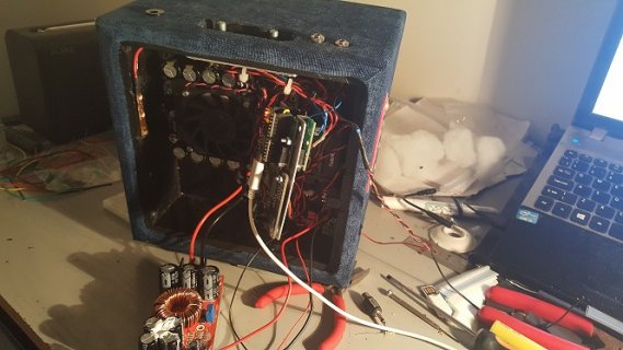
Hi I am making a modular self powered pa system for my street show and I would really appreciate a bit of help with the connections.

I have a teensy and 2 audio shields and would like to output to four unbalanced mono channels, bass, mid, high and full range, each would go to an rca connection and have a separate amp, is this doable?

Many thanks
 
Sounds pretty do-able. Just connect the wires to the line-level output signals on the two shields.

If Teensy connects to the same power (and ground) as the rest of this system, and if you get hum or strange "ground loop" noises. The solution is usually to add a ground loop isolator. Normally the headphone output shouldn't be used for connecting to other grounded stuff (see the warning on the bottom side). These isolators also separate the grounds, so you can use the headphone outputs for non-headphone connections more easily.
 
Thanks for your help, that's great!!

Funnily I already had the isolator link open, I'm hoping I wont need it because all the runs will be short but I am already getting a hum from a bluetooth board in the test setups I have tried so far. I take it I would need two of these?

I would take the ground and split it to give two rca outputs per isolator, is this correct?

Thanks for taking the time to help a newb out!
 
I have everything hooked up and working reasonably well, I still need to mount the boards properly and I have a smaller power supply and a battery arriving soon. I suspect I will have to solder some of the leads rather than using header pins.
My apologies Paul for buying the isolators elsewhere, when I came to order you were out of stock.

Managed to get most of the functionality I want, control volume and pan between input channels. I have the output to 3 mono 3.5 jacks and 1 channel to the amp. The four output channels are filtered to give, full, bass, mid, top. The mid channel going to the amp.

All this is working fine but in an ideal world I would like to adjust the frequency range to better match the speaker.

Is there a simple way to do this with filter? or would I need to use a biquad on each output channel?

smler.jpg
 
SOLVED :) Used two biquad filters on each output, one high pass, one low to tailor each one

biquad1.setHighpass(0,180,0.707);
biquad2.setLowpass(0,10000,0.707);

Still need to tinker with those values a bit but its sounding much fuller now.

Thinking to mount the boards on fibreglass or plastic instead, just in case anything comes loose .I have an IR receiver installed which I will now try and get triggering sound files from the sd, It would be great to have my show music/fx via remote.

That someone like me, without a background in electronics or programming can make this work is just amazing. Thankyou :)
 
Not quite as simple as I thought haha, working out bugs and spacing of bits and bobs. I have had to de-solder a lot of connectors to make the various modules fit. Today I decided to re-wire, as the power and signal looms were getting messy causing some noise I suspect, in spite of using the isolators.

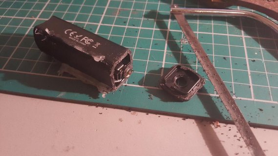
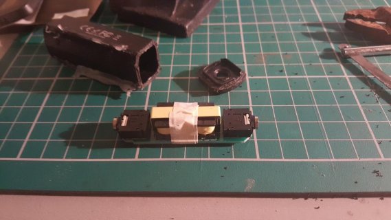
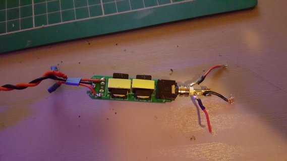
The jacks in and out of the isolators are quite bulky and so I decided to cut one open and see if I could solder directly to the board. I tried with pliers to pull the end cap off but in the end a careful cut with a hacksaw, let the board slide out. A couple of pics for the curiousiso.jpgiso1.jpg
 
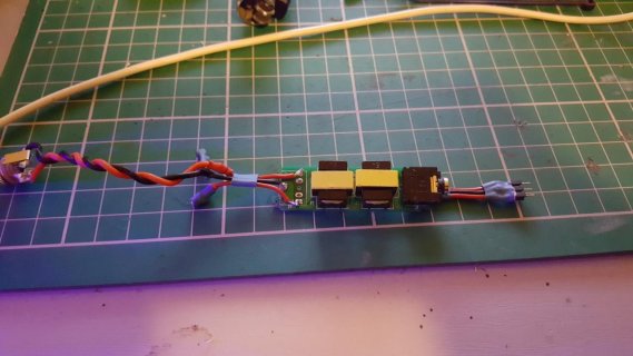
Having a few issues and hoping someone can help me understand whats going on. I rewired the isolators directly to the board, using the pins where the jack socket is soldered.
iso3.jpg


Since doing this the right and left channels are mixing. I even get audio when the channel I am connected to has no patchcord in the code.
When I bypass the isolator there is no issue, each channel is separate and no patchcord = nothing.

I must have connected to the wrong place but I can't for the life of me work it out, I have probed with the multimeter but I seem to be getting odd readings, part of which I think is an old battery but I am getting continuity between ground and the two positives, even when I connect a stripped jack to test.

iso4.jpg

I'll not be too upset if I have to ditch them but I would like to know whats going on.
 
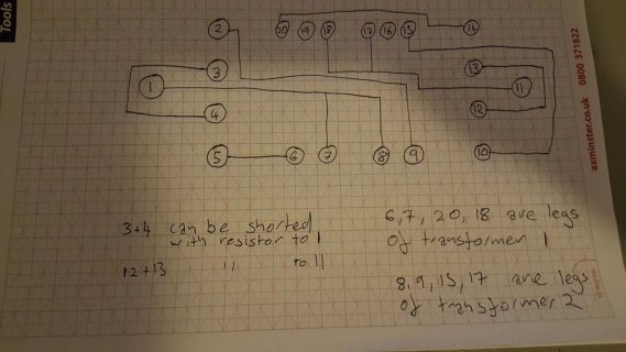
Luckily the transformers are not tight to the board and I was able to use a torch and map the pins. As far as I'm aware I have the connections correct but I think there might be something funny going on with pins 1,3,4 and 11,12,13 inside the jack sockets. I removed and dissected one but I am non the wiser, shield lift ?

iso5.jpg

I have ordered more header pins to make it easier to add or bypass these and test more thoroughly.
 
Just an update on the project, I appreciate this is probably childsplay for many on here but I have found threads like this useful in the past so I will continue to document in case it helps someone.

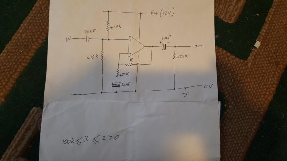
I decided to ditch the isolators. After testing I couldn't notice much difference with them in or out of the system and the main thing that has cut the interference for me has been to change the filters from biquad to chamberlain. Also the space that they take up will be useful for a small op amp circuit my stepdad helped me design to take the output from the teensy up to the max that my amps input can take. In this system volume is primary over fidelity, although I don't seem to have sacrificed any quality by doing this. Whilst I am trying to learn and do as much of the design as possible by myself , there is a huge amount of new information for me to process and I am not above seeking help to get the job done. Here is the op amp circuit, I do not pretend to understand it completely but it works :) The chip is a tl071cp opamp.jpg

I thought it would be nice to be able to tune the frequencies of the filters without having to reprogram the teensy, allowing other systems to take the output from the box and have them suit accordingly. At first I used 2 pots for this but found that a rotary encoder with a push switch, works better. In conjunction with two led's to indicate which filter is being tuned, led 1 on= highpass on one channel, led 2 on =lowpass on the second, led 1 flashing = highpass on ch 3&4 and led 2 flashing for lowpass on ch 3&4

There is a physical switch to change between bluetooth and one of the lines in and a pot to mix between the jack my mic will be plugged into and the music, be that from sd, bluetooth or jack

There is another pot to control master volume

I have the IR remote set to play different show tunes, to switch in between the different sources of music and to play sound fx over everything. I am a clown by trade so making a 100w fart machine has made me very proud. I'm gonna have a lot of fun with this!

The scope of this project keeps expanding as I realise the possibilities, I salvaged a small 10 pin lcd from a printer so I might well take out all the pots and just have the input selector switch and the encoder. This would also be useful for my next job which is to make a playlist for when I want to take the box out to play, 32gigs is a lot of storage I may as well have fun with it.

I am now working on the power system, testing and matching lithium cells, making a low voltage cut off circuit, fitting a fuse and setting up a dc in plug which cuts off the battery, so that I can run this box from the wall if I want to. I am also making a spot welder for the battery so as not to damage cells by soldering. I have enough cells to make up two 5s2p packs to be balance charged by a hobby charger off board. It's safer and I have too much invested in this to risk a fire through a faulty bms. It will also allow me to change out batteries if I need longer runtime.

My level of programming is like that of a toddler playing with leggo, most of the sketch has been lifted with much head scratching from the example sketches but it seems to be working o.k.
I am really enjoying puzzling through though and it's getting easier as I learn more. Here is the picture from the audio design tool and the sketch so far, appologies if it's a bit jumbled at the mo, I will tidy it up for the final update.
Screenshot (1).jpg
Code:
 #include <IRremote.h>
#include <Encoder.h>
#include <Bounce.h>

#include <Audio.h>
#include <Wire.h>
#include <SPI.h>
#include <SD.h>
#include <SerialFlash.h>

// GUItool: begin automatically generated code
AudioInputI2SQuad        i2s_quad2;      //xy=62.5,113
AudioPlaySdWav           playSdWav1;     //xy=69,62
AudioPlaySdWav           playSdWav2;     //xy=83,216
AudioMixer4              mixer1;         //xy=216,75
AudioMixer4              mixer2;         //xy=218,145
AudioMixer4              mixer4;         //xy=286,229
AudioMixer4              mixer3;         //xy=348,145
AudioMixer4              mixer5;         //xy=430,234
AudioMixer4              mixer6;         //xy=439,52
AudioFilterStateVariable filter3;        //xy=606,105
AudioFilterStateVariable filter4;        //xy=607,164
AudioFilterStateVariable filter1;        //xy=625,27.5
AudioFilterStateVariable filter2;        //xy=759,30
AudioOutputI2SQuad       i2s_quad1;      //xy=932,127
AudioConnection          patchCord1(i2s_quad2, 0, mixer2, 0);
AudioConnection          patchCord2(i2s_quad2, 1, mixer2, 1);
AudioConnection          patchCord3(i2s_quad2, 2, mixer1, 2);
AudioConnection          patchCord4(i2s_quad2, 3, mixer1, 3);
AudioConnection          patchCord5(playSdWav1, 0, mixer1, 0);
AudioConnection          patchCord6(playSdWav1, 1, mixer1, 1);
AudioConnection          patchCord7(playSdWav2, 0, mixer4, 0);
AudioConnection          patchCord8(playSdWav2, 1, mixer4, 1);
AudioConnection          patchCord9(mixer1, 0, mixer3, 0);
AudioConnection          patchCord10(mixer2, 0, mixer3, 1);
AudioConnection          patchCord11(mixer4, 0, mixer5, 1);
AudioConnection          patchCord12(mixer3, 0, mixer5, 0);
AudioConnection          patchCord13(mixer5, 0, mixer6, 0);
AudioConnection          patchCord14(mixer6, 0, filter1, 0);
AudioConnection          patchCord15(mixer6, 0, filter3, 0);
AudioConnection          patchCord16(mixer6, 0, filter4, 0);
AudioConnection          patchCord17(filter3, 2, i2s_quad1, 1);
AudioConnection          patchCord18(filter4, 0, i2s_quad1, 2);
AudioConnection          patchCord19(filter1, 0, filter2, 0);
AudioConnection          patchCord20(filter2, 2, i2s_quad1, 3);
AudioConnection          patchCord21(filter2, 2, i2s_quad1, 0);
AudioControlSGTL5000     sgtl5000_1;     //xy=69,21
AudioControlSGTL5000     sgtl5000_2;     //xy=219,20
// GUItool: end automatically generated code


#define SDCARD_CS_PIN    10
#define SDCARD_MOSI_PIN  7
#define SDCARD_SCK_PIN   14

#define NUM_BUTTONS   7       // number of remote buttons
#define RECV_PIN      5


const int ledPin1 =  4;
const int ledPin2 =  3;

uint16_t lastCode = 0;
const uint16_t BUTTON_1 = 0xFF30CF; //ir remote codes
const uint16_t BUTTON_2 = 0xFF18E7;
const uint16_t BUTTON_3 = 0xFF7A85;
const uint16_t BUTTON_STOP = 0xFF629D;
const uint16_t BUTTON_SD = 0xFFA25D;
const uint16_t BUTTON_LINE = 0xFFE21D;
const uint16_t BUTTON_FART1 = 0xFF52AD;

elapsedMillis blinkTime;
 
Bounce button2 = Bounce(2, 15);  // 15 = 15 ms debounce time

IRrecv irrecv(RECV_PIN);
decode_results results;

Encoder myEnc(20, 21);

int chfreqsel = 1;

int fil1 = 5000;
int fil2 = 800;
int fil3 = 136;
int fil4 = 11000;

long oldPosition1  = 0;
long newPosition;

void setup() {
  
  AudioMemory(60);
  
  Serial.begin(9600);
 
  
  irrecv.enableIRIn(); // Start the receiver
  pinMode (RECV_PIN, INPUT);
   
  pinMode(ledPin1, OUTPUT);
  pinMode(ledPin2, OUTPUT);
  
  pinMode(2, INPUT_PULLUP);
  
  SPI.setMOSI(SDCARD_MOSI_PIN);
  SPI.setSCK(SDCARD_SCK_PIN);
  if (!(SD.begin(SDCARD_CS_PIN))) {
    while (1) {
      Serial.println("Unable to access the SD card");
      delay(500);
    }
  }
  

  sgtl5000_1.setAddress(LOW);
  sgtl5000_1.enable();
  sgtl5000_1.lineOutLevel(13);
  sgtl5000_1.lineInLevel(9);
  sgtl5000_1.muteHeadphone();
   
  sgtl5000_2.setAddress(HIGH);
  sgtl5000_2.enable();
  sgtl5000_2.lineOutLevel(13);
  sgtl5000_2.lineInLevel(9);
  sgtl5000_2.muteHeadphone();
  
 // midrange output

  filter2.frequency(136);
  filter1.frequency(11000);

 // toprange output
  filter4.frequency(5000);
  
 // lowrange output
 filter3.frequency(800);
 
 // sd music in
  mixer1.gain(0, 0.0);
  mixer1.gain(1, 0.0);
  
 // line1/bluetooth
  mixer1.gain(2, 0.5);
  mixer1.gain(3, 0.5);
  
 // line2/mic  
  mixer2.gain(0, 0.5);
  mixer2.gain(1, 0.5);
  
 // mix line2/mic with sd/line1
  mixer3.gain(0, 0.5);
  mixer3.gain(1, 0.5);
 
 // sd fx
  mixer4.gain(0, .5);
  mixer4.gain(1, .5);
  
 // mixes sd fx and line/sd 
  mixer5.gain(0, .5);
  mixer5.gain(1, .5);

 //master volume
  mixer6.gain(0, 0);
  }

void loop() {
   
   button2.update();
  if (button2.fallingEdge()) {
    chfreqsel  ++ ;
    if (chfreqsel == 5) chfreqsel = 1;
  }
  
  if (chfreqsel == 1){
  digitalWrite(ledPin1, HIGH);
  digitalWrite(ledPin2, LOW);
  
    long newPosition = myEnc.read()/4;
  if (newPosition != oldPosition1) {
   oldPosition1 = newPosition;
  // Serial.println(newPosition);
 
    fil1 = fil1 + newPosition * 10;
   
    if (fil1>20000){
      fil1 = 20000;}
      if (fil1<20){
      fil1 = 20;}
       Serial.println(fil1); 
   filter4.frequency(fil1);
    
   myEnc.write(0);}
 }
 
  if (chfreqsel == 2){
  digitalWrite(ledPin1, LOW);
  digitalWrite(ledPin2, HIGH);
     long newPosition = myEnc.read()/4;
  if (newPosition != oldPosition1) {
   oldPosition1 = newPosition;
  // Serial.println(newPosition);
 
    fil2 = fil2 + newPosition * 10;
   
    if (fil2>20000){
      fil2 = 20000;}
      if (fil2<20){
      fil2 = 20;}
       Serial.println(fil2); 
   filter3.frequency(fil2);
    
   myEnc.write(0);}
} 

 if (chfreqsel == 3){
  digitalWrite(ledPin2, LOW);
  if (blinkTime < 250) {
    digitalWrite(ledPin1, LOW);
  } else if (blinkTime < 500) {
    digitalWrite(ledPin1, HIGH);
  } else {
    blinkTime = 0; 
  }
     long newPosition = myEnc.read()/4;
  if (newPosition != oldPosition1) {
   oldPosition1 = newPosition;
  // Serial.println(newPosition);
 
    fil3 = fil3 + newPosition * 10;
   
    if (fil3>20000){
      fil3 = 20000;}
      if (fil3<20){
      fil3 = 20;}
       Serial.println(fil3); 
    filter2.frequency(fil3);
    
   myEnc.write(0);}
 }
 
if (chfreqsel == 4){
  digitalWrite(ledPin1, LOW);
if (blinkTime < 250) {
    digitalWrite(ledPin2, LOW);
  } else if (blinkTime < 500) {
    digitalWrite(ledPin2, HIGH);
  } else {
    blinkTime = 0; 
  }
   long newPosition = myEnc.read()/4;
  if (newPosition != oldPosition1) {
   oldPosition1 = newPosition;
  // Serial.println(newPosition);
 
    fil4 = fil4 + newPosition * 10;
   
    if (fil4>20000){
      fil4 = 20000;}
      if (fil4<20){
      fil4 = 20;}
       Serial.println(fil4); 
    filter1.frequency(fil4);
    
   myEnc.write(0);}
 }
 
  {
 // Pan between line1/sd music and mic while allowing sd fx to play over both 
  int knob1 = analogRead(A3);  
  float gain1 = (float)knob1 / 1023.0;
  float gain2 = 1.0 - gain1;
  
 // line1/sd in
  mixer3.gain(0, gain1 );
  
 // mic/line2 in 
  mixer3.gain(1, gain2 );
  
 // Master volume
  int knob = analogRead(A2);
  float vol = (float)knob / 1023.0;
  mixer6.gain(0,vol);
  //Serial.print("volume = ");
 // Serial.println(vol);
}

// ir buttons and decoder 
{
  if (irrecv.decode(&results)) {
    uint16_t resultCode = (results.value & 0xFFFF);
    if (resultCode == 0xFFFF)
      resultCode = lastCode;
    else
      lastCode = resultCode;
    switch (resultCode)
    {
      case BUTTON_1:
         if (playSdWav1.isPlaying() == false) 
  //  Serial.println("Start playing1");
    playSdWav1.play("FIRE1.WAV");
    delay(10); // wait for library to parse WAV info
        break;

      case BUTTON_2:
         if (playSdWav1.isPlaying() == false) 
  //  Serial.println("Start playing2");
    playSdWav1.play("FIRE2.WAV");
    delay(10); // wait for library to parse WAV info
        break;
        
      case BUTTON_3:
         if (playSdWav1.isPlaying() == false) 
  //  Serial.println("Start playing3");
    playSdWav1.play("FIRE3.WAV");
    delay(10); // wait for library to parse WAV info
        break;
      
      
      case BUTTON_STOP:
         if (playSdWav1.isPlaying() == true) 
 //   Serial.println("Stop");
    playSdWav1.stop();
    playSdWav2.stop();
 //   delay(10); // wait for library to parse WAV info
        break;
        
        case BUTTON_SD:
         // sd music in
    mixer1.gain(0, 0.5);
    mixer1.gain(1, 0.5);
 // line1/bluetooth
    mixer1.gain(2, 0);
    mixer1.gain(3, 0);
  //  Serial.println("SD ON, LINE ONE OFF");
         break;
         
        case BUTTON_LINE:
         // sd music in
    mixer1.gain(0, 0.0);
    mixer1.gain(1, 0.0);
   // line1/bluetooth
    mixer1.gain(2, 0.5);
    mixer1.gain(3, 0.5);
   // Serial.println("SD OFF, LINE ONE ON");
      break;
      
   
      case BUTTON_FART1:
         if (playSdWav2.isPlaying() == false) 
        // Serial.println("FART2");
          playSdWav2.play("FART2.WAV");
          delay(10); // wait for library to parse WAV info
           break;


      default:
        Serial.print("Unrecognized code received: 0x");
        Serial.println(results.value, HEX);
        break;
    }

    irrecv.resume();
  }
}
 
}
 
Thanks Paul, getting addicted haha!

I do have a couple of questions I couldn't find the answer to in the documentation, if you or anyone else can help it would be great.

Is there any way to judge how much audio memory to assign? I picked a random number and I'm not having any problems but is it just trial and error?

I have two sd slots with the shields, would it be better to have my fx on one and my music on another to avoid possible conflicts whilst playing both together. I have had things freeze up once but only when spamming the fx, won't be a problem in normal operation but I'd like to remove the posibility if I can.
 
... to change the filters from biquad to chamberlain. Also the space that they take up will be useful for a small op amp circuit my stepdad helped me design...
I'm not a frequent viewer here, but I don't know what a "chamberlain" filter is. I do know about the biquad.

Did your stepdad work on vacuum tubes?
The resistor values of your opamp circuit reminded me of those days. They could be cut by a factor of 10 - which means the capacitors should be raised by a factor of 10. This could also reduce hum.
 
I may have the name of the filter mixed up, sorry for any confusion . They are refered to in the documentation and after googling and reading I was non the wiser untill I found a thread on here refering to them as such. They are the first filter in the design tool if that helps. I'm away from home working at the moment and on my phone so I'm not sure exactly what thread I was reading.

He did learn his electronics a long time ago and has an obsession with classic sounding guitars so it's not surprising if it's a bit old school. He had most of the parts on hand, I only needed to order the chip but it's working well. I'm reluctant to spend more time on it tbh. I want to finish the project and there is still a lot of work to do. The noise I had was more of a high end whistling/windy noise, which thankfully has gone.

Pardon my ignorance but would changing the values increase current draw? This will mostly be run from batteries and the more efficient the better.
Thanks.
No its not a serious issue, just an observation on my part. It wouldn't significantly change the total current as most of the current is consumed by the IC.
 
Status
Not open for further replies.
Back
Top