Teensy 3.2 + USB Host Shield

Status
Not open for further replies.

neroroxxx

Well-known member
Hey guys, i was wondering if could get some feedback on a design.

I'm using a teensy 3.2 and a USB Host Shield Mini along with 2 amphenol usb jacks, a micro for the teensy and a Type A for the host shield. They will all be solder onto a custom PCB.

The usb jack on the host shield will be removed and then i'll wire the Gnd, D-/+ pins on the Host shield board to the custom PCB and those would be routed to the Amphenol Type A jack. For the Teensy i'll use the D-/+ pads and the VUSB pin.


My first question is, Is it ok to wire the VUSB pin to the Vcc of both amphenol jacks, the micro and type A?


So basically the USB power comes from the Micro USB jack and from there it's split to the VUSB pin of the Teensy to power it and the Vcc pin of the Type A amphenol jack to power the midi device connected. The Host shield would still receive 3v3 from the Teensy but that signal would not be connected to the Type A Jack.

Wow this was a lot harder to explain than I thought it would be! I'm attaching a screenshot of the PCB design to try and make sense of the question.


My second question is, do i still have to use a 100uF capacitor from 3v3 to ground? I'm assuming the answer to this would be yes but i would like to confirm.

Thank you in advance for your help!
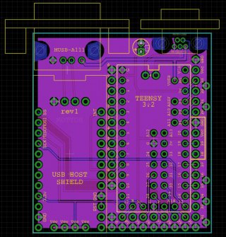
Screen Shot 2017-08-19 at 12.01.36 PM.jpg
 
The right answer for the 5V is 'no' in that technically you should have the host controlling the current to the USB device after negotiating how much was available and how much the device needed. In practice if you know how much current your midi device draws, and that it won't exceed the 500mA(-teensy current draw) the computer->Teensy link can provide then it will probably work, in theory the midi device should not draw more than 100mA until told it can do so, but suspecting it's not that carefully engineered so the only worry is the total current draw from your PC, especially when first plugged in where teensy+hostshield+midi device will all be drawing current to charge up filter caps etc.

What is the source that stated needing the 100uF cap?
 
Ok, makes sense now.

USB standard specifies that hosts will have a decent sized capacitance on the 5V rail to handle surges as devices are plugged in
The design shown actually feeds 3.3V to the connected USB device (hence notes that this may not work).
In this setup you need a good sized cap to stop a connected USB device browning out the Teensy and/or USB shield and crashing them

In your setup, similar to what is described further down the page as a better setup where you have 5V powering 5V things (not 3.3 to a the 5V USB device) and the Teensy+host shield on 3.3V you need the cap on the 5V side. And if you are really sure your Midi device is self powered then you may not even need it. Simple test would be to hack a USB cable and check the actual current demand with a meter.
 
The most difficult issue is what happens when you hot plug a USB device. The discharged power supply capacitors inside the device are suddenly shorted (through the low resistance + inductance of the cable) together to the charged power supply caps in the host. Some of the host capacitor charge flows away quickly to the device, causing a sudden drop in the host's voltage.

The USB spec says the host must have at least 120 uF and the device must not have more than 10 uF. Both sides are supposed to be low ESR & ESL. That combination limits the host's voltage drop to a safe amount, and limiting the inductance helps control high frequency oscillations immediately following the hot plug event.

The USB spec also says the device may have more capacitance, as long as it has some sort of (unspecified) input current limiting circuitry that prevents the host from ever seeing a load equivalent to 10 uF in parallel with 50 ohms (the resistor that would draw the max 100 mA allowed during enumeration).

Fully meeting all this is quite difficult, and expensive, when your only power source is as a USB device and you need to act as another USB host. On Teensy 3.6, I went with a "close enough" (at least hopefully close enough) solution using a current limit switch and a 100 uF capacitor. I tested larger caps, but with the fairly high limit, it put too much drain on the host's voltage. So the 3.6 circuit is compromise. Might be worth considering.

Or you could omit the 100 uF or 120 uF capacitor if you're sure you'll never hot plug. But realistically, USB is all about hot plugging....
 
Thank you Paul, the only issue i've had so far is that sometimes if i connect a USB device to the USB Host shield with a teensy, the USB device is not recognized, the easy fix is to unplug it and plug it back in.

I would prefer using the USB host on the teeny 3.6 which i've tested but the MIDI driver is not complete, hopefully once it's complete i would never need a host shield!
 
I would prefer using the USB host on the teeny 3.6 which i've tested but the MIDI driver is not complete

Can you tell me how you're going to use the MIDI driver?

I am *still* searching for a USB MIDI product (not another Teensy or other dev board) that receives messages over USB MIDI and does something observable with them.
 
I'm using the USB Host shield to send/receive sysex messages to control a guitar processor (Fractal AX8) basically i'm creating and expansion board to that guitar processor.

Many guitar processors now have midi over usb and at the least can be controlled by PC and CC

I have an Eleven Rack which has midi over USB which i wouldn't mind lending you if it would help the development of the host usb midi class, i'll see what other options are out there for products that have it and are more accessible
 
Can you tell me how you're going to use the MIDI driver?

I am *still* searching for a USB MIDI product (not another Teensy or other dev board) that receives messages over USB MIDI and does something observable with them.

MidiOx (windoze - free program) can tell you a lot about USB MIDI traffic.
 
Status
Not open for further replies.
Back
Top