120000 lumens, 42A @ 24V, PWM

Status
Not open for further replies.

benscammell

Well-known member
So I am doing some garage lighting, and I have 25m of this:-

LED Strips on AliExpress

And one of these to power them:-

PSU on AliExpress

Which should yield about 120000 lumens in my 6m x 6m garage using 1000W @ 42A / 24V.

I would like to be able to dim it, and feel PWM is the answer.

Any thoughts / advice on doing PWM with a Teensy on a large LED array like this?

Thanks in advance,

Ben
 
lots of mosfets and pca9685's (free running) can do the job, allows you to put teensy to sleep/reprogram without changing your lighting
 
lots of mosfets and pca9685's (free running) can do the job, allows you to put teensy to sleep/reprogram without changing your lighting

Yep, I'm looking at BUZ11's off PCA9685. I'm going to make it modular, so you can chain the "driver" PCB's over I2C driven from one Teensy (probably a 3.6, as I've not played with one yet). e.g. you can do 16, 32, 48 etc. channels as required.

I need 25 channels of PWM, as I want to be able to silly effects lol

Ben
 
The FET's are good to 50V@30A, and the strips are 24V to get the current down, I'd use 48V if they made them.... as at full power the array will consume 42A total, about 1.8A/m... so I'm "well in" with BUZ11.

Ben
 
You actually don't need a Teensy for this, a normal Arduino could do this just as well. The PCA9685 does not need any heavy external hardware to control it.
The BUZ11 will have a different RDS(on) at 5V then say 10V gate so be mindful of that, the datasheet does not give numbers at sub 3A currents.
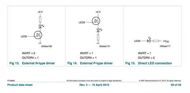
Make sure you have the PCA9685 set up for Totem pole operation(OUTDRV in datasheet), you have to drive the fet gate high and low. Most PCA9685 boards have resistors in series with the PWM outputs, you may have to change them, the higher the resistance the slower the gate is turned on/off meaning your turning the Fet into a heater in those regions.

If you set it up correctly you will only get around 10-12C rise from the BUZ11 running 1.8A.

Can you think of a better FET to use? I’m switching 24V and 2A per channel...

I’ll be designing a custom PCB for it, so any schematic advice greatly received!

Thanks, Ben
 
The BUZ11 will probably work but its tough, based on the Datasheet the VGSth is going to be close to the driving voltage from the PCA9685. You can either test it or pick something with lower VGSth. I find Digikey has a pretty decent website for searching for parts.
The PCA9685 has an absolute max voltage of 6V. So most likely you will be using a 5V supply to power it. Which means your gate voltage will be 5V max, probably closer to 4.5V based on the datasheet.
Your gate resistors will probably have to be between 200-400R based on datasheet ratings for the PCA. Larger means slower turn on/turn off= more heat into fet. Lower means higher risk of damage to the chip if something goes wrong, your system seems conservative so unless you short a fet by accident you should be safe going low.

Do you really need a gate resistor?

Screen Shot 2017-08-27 at 16.52.26.jpg

SCH on p29 of the datasheet suggest you can do without...

PCA9685 Datasheet

Thoughts?
 
you dont need it i would presume since the pca is always driving it HIGH/LOW and not leaving itnin high-z state, not sure effects of having the pca9685 powered off on the iutput state though
 
The purpose of the gate resistor is to protect the driver(PCA9685). To the driver the Fet looks like a capacitor, your rapidly charging and discharging it, without current limiting you could damage the driver.
 
theres a difference between the gate resistor to GND and gate resistor in series to pca9685
some people dont even use any
there have been no reports of people killing them without resistors by ommitting the gate resistor, same with mcus
 
@tonton81, I never once mentioned a pull-down resistor on the gate.
If your referring to people using pre-built PCA9685 boards, the boards that I have seen sold have those resistors already.
As an Electronics Engineer I find it dangerous to assume that damage wont occur over time, I have to design and plan for 20 year lifespans.
Manufacturers give ratings for a reason, if we choose to ignore them then its on us to clean up the mess.

I'm not trying to ignore things, I'm just not that skilled as to know the right answer. :)

Here's my schematic, any comments would be greatly appreciated.


Thanks, Ben
 

Attachments

  • v1.0 I2C PWM LED (16ch, 60v, 35a) Controller SCH.pdf
    42 KB · Views: 124
I'm not trying to ignore things, I'm just not that skilled as to know the right answer. :)

Here's my schematic, any comments would be greatly appreciated.

Thanks, Ben

Looks pretty standard, few comments.

STD30NF06L is much better, especially with 3.3V. Much lower RDS also, you should be good with the DPAK versions.
Gate resistors will limit current to 33mA, which should be fine.
/OE is Active LOW, meaning it will be on unless you drive it HIGH. Normal setup is to put a pull-up on Active LOW so it gets pulled HIGH on startup so if something goes wrong with the micro it will be disabled.
Not sure about the EXTCLK pin, if i'm reading the datasheet correctly the fastest LED PWM you can get is about 4KHz with a 50MHz external clock.
Consider adding a 0.1uF and a 10-47uF capacitor to the board. Both near the PCA9685 to provide for inrush current and noise limiting during switching. The larger cap size is limited by the Teensy 3.3V power supply, to large of a cap can cause startup issues.
Do you know what Teensy or other Micro your going to use?

Thank you for your help, most appreciated!

I'm using a custom Teensy implementation using the MK20DX256 uC. I don't use the internal regulator, instead an external 3.3v 1A LDO reg.

I've attached an updated SCH & BRD, taking into account your thoughts. Am I about there?

SCH - View attachment v1.0 I2C PWM LED (16ch, 60v, 35a) Controller SCH v0.2.pdf
BRD - View attachment v1.0 I2C PWM LED (16ch, 60v, 35a) Controller BRD v0.2.pdf

Thanks, Ben
 
Getting close.

1. R1-R6 and R23 can just be 10K.
2. I don't recommend daisy chaining your power connections. I would use 2 large screw posts for each board and run dedicated power to each with heavy wires. Try looking for something like these which are rated for 30A. You can use 2x12AWG wires or an 8AWG to power each board. Ive seen enough of those green terminals catch fire on 3D Printers to stay well clear of them for high current applications.
3. The thermal vias at your power connectors are way to small. I use this tool to give me an idea of how thick traces need to be to reduce excess heating.
4. Depending on wire distance from PSU you may also need some large electrolytic's on the board.

1. R1-R6 + R23 are marked as 10K now on SCH.
2. I've used those connectors, and I've left a pair of output ones, which will likely be unpopulated, but "just in case".
3. I've got rid of thermals entirely, time to break out the 100W soldering iron!

The PSU will be circa 30cm of 8-12AWG wire away, do you think I need some big electrolytics? I'd rather add now, and not populate, than have to re-spin the PCB.

What size would you go for?

Thanks, Ben
 

Attachments

  • v1.0 I2C PWM LED (16ch, 60v, 35a) Controller SCH v0.3.pdf
    23.3 KB · Views: 119
  • v1.0 I2C PWM LED (16ch, 60v, 35a) Controller BRD v0.3.pdf
    153.4 KB · Views: 100
Updated with 4x 1000uF 50V Electrolytics.
 

Attachments

  • v1.0 I2C PWM LED (16ch, 60v, 35a) Controller v0.4 BRD.pdf
    156.7 KB · Views: 136
Its not something I can easily answer, leave room to go one size bigger if you have to. I will say you should keep them close to the input side connections. So put all 4 close to the input side.
You should have some small thermal vias or it will be a real pain trying to soldier the connections.
 
Its not something I can easily answer, leave room to go one size bigger if you have to. I will say you should keep them close to the input side connections. So put all 4 close to the input side.
You should have some small thermal vias or it will be a real pain trying to soldier the connections.

Thanks for all your help.

Fancy reviewing a few other SCH's? :)
 
Status
Not open for further replies.
Back
Top