Change I2C bus for TCS34725

Status
Not open for further replies.

Anton_H

Active member
Hi,


Since I need 2 TCS34725 sensors, I wanted to know how to read the data of a TCS34725 RGB-color sensor from the second I2C bus of my Teensy3.6. I didn't found anything on internet, apart from a mutiplexer, wich will be difficult to use in my project.

I tried to do <Wire1.begin();> in the begin of my code, but then the code freezes at <if(tcs.begin)>. I asked on the adafruit forum(https://forums.adafruit.com/viewtopic.php?f=19&t=122675), and they said that this should normally works, so I had to ask here.

If it is not possible to use it with the library of the sensor, can someone provide me the code to get data from the sensor without the library please? I found some codes on internet but none of them worked for me.


Thanks very much in advance,

Anton
 
you need to modify the library to use another Wire port, but then you break the original port access, the multiplexer is a good idea, however, if you want to run a DIFFERENT library for your sensor that will be okay too
 
Hi,

Thanks for your help! With the first library I got it working on the first I2C bus (with the <i2c_t3> library in case of <Wire.h>). To get it working on the second I2C bus, I replaced all the <Wire.something> by <Wire1.something>. But my code hangs here:

void init_TCS34725(void)
{
i2cWriteBuffer[0] = 0x00;
//i2cWriteBuffer[0] = 0xff;
Writei2cRegisters(1,ATimeAddress); // RGBC timing is 256 - contents x 2.4mS =
i2cWriteBuffer[0] = 0x00;
Writei2cRegisters(1,ConfigAddress); // Can be used to change the wait time
i2cWriteBuffer[0] = 0x00;
Writei2cRegisters(1,ControlAddress); // RGBC gain control
i2cWriteBuffer[0] = 0x03;
Writei2cRegisters(1,EnableAddress); // enable ADs and oscillator for sensor
}

I think it is because the commands are with <Write> and not <Write1>. Can you say me how to program this for the second I2C bus? (I hope I was clear).

Thanks in advance
 
No, I installed it like I do it for all the other libraries. But where is the Wire.h and Wire.cpp file? I don't find them.
 
they are "#include"'d inside the library's H and CPP file

do dont only change Wire. to Wire1. but also the include at the top of the library files to the i2c library for teensy as well
 
like instead of include Wire.h do include i2c_t3.h or whatever the naming convention is :)

it looks like your using the first code on the github link so change this
#include <Wire.h>

to your teensy i2c library

#include <i2c_t3.h>

the second i2c bus is Wire1. (not write1)
 
Last edited:
I thought I had to change it in the directory were I install my libraries :). So yes I did #include <i2c_t3.h> in the begin of my code and delete #include<Wire.h>.
And yes I read write in place wire :), sorry.
 
can you post your sketch? i dont think you replaced all of the Wire. references, you must also do Wire.begin() and Wire1.begin() in setup to initialize both busses
 
I was just trying to get the second bus working. In void.setup(), I printed numbers on the serial monitor, to see were my code hangs. Numbers 1 and 2 appears.

Code:
/*
This program interfaces to the AMS TCS34725 color light
to digital converter IC.  It uses the Arduino I2C interface.  
*/

#include <i2c_t3.h>
//#include <Wire.h>
#include <Math.h>

byte i2cWriteBuffer[10];
byte i2cReadBuffer[10];

#define SensorAddressWrite 0x29 //
#define SensorAddressRead 0x29 // 
#define EnableAddress 0xa0 // register address + command bits
#define ATimeAddress 0xa1 // register address + command bits
#define WTimeAddress 0xa3 // register address + command bits
#define ConfigAddress 0xad // register address + command bits
#define ControlAddress 0xaf // register address + command bits
#define IDAddress 0xb2 // register address + command bits
#define ColorAddress 0xb4 // register address + command bits

unsigned long count = 0, t_start = 0, t_end = 0, t_sum = 0;

  unsigned int clear_color = 0;
  unsigned int red_color = 0;
  unsigned int green_color = 0;
  unsigned int blue_color = 0;
/*  
Send register address and the byte value you want to write the magnetometer and 
loads the destination register with the value you send
*/
void Writei2cRegisters(byte numberbytes, byte command)
{
    byte i = 0;

    Wire1.beginTransmission(SensorAddressWrite);   // Send address with Write bit set
    Wire1.write(command);                          // Send command, normally the register address 
    for (i=0;i<numberbytes;i++)                       // Send data 
      Wire1.write(i2cWriteBuffer[i]);
    Wire1.endTransmission();

    delayMicroseconds(100);      // allow some time for bus to settle      
}

/*  
Send register address to this function and it returns byte value
for the magnetometer register's contents 
*/
byte Readi2cRegisters(int numberbytes, byte command)
{
   byte i = 0;

    Wire1.beginTransmission(SensorAddressWrite);   // Write address of read to sensor
    Wire1.write(command);
    Wire1.endTransmission();
    
    delayMicroseconds(100);      // allow some time for bus to settle      

    Wire1.requestFrom(SensorAddressRead,numberbytes);   // read data
    for(i=0;i<numberbytes;i++)
      i2cReadBuffer[i] = Wire1.read();
      
    Wire1.endTransmission();
    
    delayMicroseconds(100);      // allow some time for bus to settle      
}  

void init_TCS34725(void)
{
  i2cWriteBuffer[0] = 0x00;
  //i2cWriteBuffer[0] = 0xff;
  Writei2cRegisters(1,ATimeAddress);    // RGBC timing is 256 - contents x 2.4mS =  
  i2cWriteBuffer[0] = 0x00;
  Writei2cRegisters(1,ConfigAddress);   // Can be used to change the wait time
  i2cWriteBuffer[0] = 0x00;
  Writei2cRegisters(1,ControlAddress);  // RGBC gain control
  i2cWriteBuffer[0] = 0x03;
  Writei2cRegisters(1,EnableAddress);    // enable ADs and oscillator for sensor  
}

void get_TCS34725ID(void)
{
  Readi2cRegisters(1,IDAddress); 
  if (i2cReadBuffer[0] = 0x44)
    Serial.println("TCS34725 is present");    
  else
    Serial.println("TCS34725 not responding");    
}

/*
Reads the register values for clear, red, green, and blue.
*/

void get_Colors(void)
{

  Readi2cRegisters(8,ColorAddress);
  clear_color = (unsigned int)(i2cReadBuffer[1]<<8) + (unsigned int)i2cReadBuffer[0];
  red_color = (unsigned int)(i2cReadBuffer[3]<<8) + (unsigned int)i2cReadBuffer[2];
  green_color = (unsigned int)(i2cReadBuffer[5]<<8) + (unsigned int)i2cReadBuffer[4];
  blue_color = (unsigned int)(i2cReadBuffer[7]<<8) + (unsigned int)i2cReadBuffer[6];

  //t_end = millis();

  //t_sum = t_sum + t_end - t_start;
  
  // send register values to the serial monitor 

  
  if(count == 100) {
    count = 0;
    t_end = millis();
    
    Serial.print("t_end - t_start:");
    Serial.println(t_end - t_start, DEC);

    t_start = t_end;
    t_sum = 0;
  }
  count++;
  
  Serial.print("clear color=");
  Serial.print(clear_color, DEC);    
  Serial.print(" red color=");
  Serial.print(red_color, DEC);    
  Serial.print(" green color=");
  Serial.print(green_color, DEC);    
  Serial.print(" blue color=");
  Serial.println(blue_color, DEC);


 // Basic RGB color differentiation can be accomplished by comparing the values and the largest reading will be 
 // the prominent color

/*
  if((red_color>blue_color) && (red_color>green_color))
    Serial.println("detecting red");
  else if((green_color>blue_color) && (green_color>red_color))
    Serial.println("detecting green");
  else if((blue_color>red_color) && (blue_color>green_color))
    Serial.println("detecting blue");
  else
    Serial.println("color not detectable");
*/
}  

void setup() {
  Serial.begin(9600);  // start serial for output
  Serial.println("1");
  Wire1.begin(I2C_SLAVE, 0x29, I2C_PINS_37_38, I2C_PULLUP_EXT, 400000);
  Serial.println("2");
  init_TCS34725();
  Serial.println("3");
  get_TCS34725ID();     // get the device ID, this is just a test to see if we're connected
  Serial.println("4");
  t_start = millis();
}

void loop() {
    get_Colors();
    
    //delay(1000);
}
 
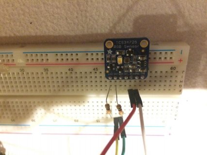
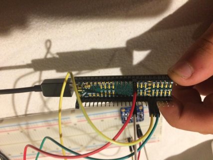
make sure the sda/scl lines are not connected wrong way, i dont see anything else so far, how is it wired?
 
It looks like the foto's are turned 180°

IMG_1007.jpg
IMG_1008.jpg
 
Okay, I finally got it working.
First I had a problem in my wiring (wrong line on my breadboard).
Second, when I use the pull up resistors, I only get the max values. So I delete them.
Third, when I use
Code:
Wire.begin(I2C_SLAVE, 0x29, I2C_PINS_18_19, I2C_PULLUP_EXT, 400000);
I only get the max values, but when I use
Code:
Wire.begin();
everything works fine.

Thank you very very much for your time and help. You gave me the code that I'm using now and you show me that there was an issue in my wiring. Thank you.
 
wait, of course it wouldnt have worked, your not i2c master, you did I2C_SLAVE

You can put that line back and put it as master, the slave wouldnt work asnits not supposed to control the clock line of the bus...
 
remove this:
Wire.begin(I2C_SLAVE, 0x29, I2C_PINS_18_19, I2C_PULLUP_EXT, 400000);

then add these:
Wire.begin(I2C_MASTER, 0x00, I2C_PINS_18_19, I2C_PULLUP_EXT, 400000);
Wire1.begin(I2C_MASTER, 0x00, I2C_PINS_37_38, I2C_PULLUP_EXT, 400000);
 
Status
Not open for further replies.
Back
Top