Processor Selection for Audio Analysis

Status
Not open for further replies.

rickso234

New member
Looking for a processor to perform FFT and digital filtering of music for beat detection, from 40Hz to 10kHz, for a potential lighting product. A key need is fast response, no longer than 10msec, preferably around 5msec per measurement loop. Plan to implement a combination of Goertzel/IIR filters for specific frequencies or narrow ranges, and a wide-bin FFT for the remainder of the spectrum. Capture and analysis of a 40Hz signal takes at least 1 cycle (25msec) but looking mainly for signal presence, not amplitude accuracy, so hoping to detect an amplitude change in less than a full cycle.

From experimentation, an Arduino/Nano just doesn't have the horsepower or memory for FFT or digital filters. Have used analog filters and peak detectors, but they're too much effort to implement in any quantity. Since it's already familiar and I have existing code, want to keep with the Arduino IDE and looking at either an "enhanced" Arduino (Due, M0) or a Teensy 3.2. Expect these processors can all run existing Goertzel/IIR and FFT algorithms, but don't know how flexible they are relative to sample rates and FFT sizes. The Teensy audio library seems tailored around the 44kHz sample rate so may not be very flexible.

Any suggestions on what processor would be better for these needs?
 
With a switched capacitor filter at 50 Hz, seeing 50Hz detection in as little as 10-15msec but not consistently... sometimes it's up to 30msec.

Does the Teensy Audio Library have the ability to use different ADC sample rates? Have any beat detection utilities been added?
 
I think you need to solve your approach first (choose an algorithm and sampling rate) then find a processor that can meet those realtime requirements.

FFTs of higher frequencies are easy and low latency if you use short windows. It's the low-frequencies that cause problems.

Since you're interested in presence, and you're not doing audio synthesis you might be able to get away with digital lock-in amplifier techniques. Here's a brief summary of how it works.

The math actually applies to complex sinusoids, but I am going to pretend bend the truth a bit and just talk about sinewaves because they're easier to understand the the idea still works.

Recall that sin(A) * sin(B) = sin(A+B) + sin(A-B)

Let's say you you are interested in signals near 40 Hz. You multiply (modulate) the audio signal with a 40 Hz sine wave. This results in sum and difference frequency generation in the output result.

Example.

Step 1) Say the input signal has a component at 46 Hz. You modulate with 40 Hz sinewave of unit amplitude (via precomputed lookup table) and you will generate 40+46 = 86 Hz and 46-40 = 6 Hz in the output signal with the same amplitude as the input component.
Step 2) You lowpass filter the output with cutoff of say, 20 Hz and check the amplitude of the output. Anything within 20 Hz of your 40 Hz sinewave will remain after the lowpass filter, Everything else is filtered out. Keep in mind real filters are not brickwalls though.

Let's call the frequency of the modulation sinewave X, and the bandwidth of the lowpass filter Y.

If the input signal has any "significant" frequencies within the range (X-Y) to (X+Y), the amplitude out of the lowpass filter will be "significant", otherwise it will be near zero.

In layman's terms, say you are interested in neighorhood around a particular frequency. Using a modulation sinewave, you cast a net around that frequency, then drag it down to near DC (via difference generation) where you can easily filter out what you're interested in. If there were not input frequency components in the range of your "net" the ouptut of the lowpass filter will be very low, basically just the broadband noise.

You need to repeat this for every frequency you're interested in, so select a few target frequencies in the lower area where FFT's are a pain, and cast nets of appropriate width so they cover the lower spectrum.

The modulation is really cheap (just a multiply) if you use precomputed lookup tables for the sin(X) modulator frequencies of interest. It's the low-pass filtering requirements that consume most of the CPU cycles, but is still probably cheaper, and lower latency than big FFT windows.

Btw, I think for the price, a Teensy 3.6 can't be beat for DSP processing.
 
Last edited:
Quite an interesting idea...

Anything within 20 Hz of your 40 Hz sinewave will remain after the lowpass filter,
With a 20Hz lowpass, wouldn't this be anything less than 20 Hz?

Assume your filters are digital. Guess I'm not seeing what the modulation gains over just having a say 45Hz lowpass filter or a Goertzel centered at 40 Hz.

Using a modulation sinewave, you cast a net around that frequency, then drag it down to near DC (via difference generation) where you can easily filter out what you're interested in.

I thought the lower the frequency, the harder (and longer) it is to filter and detect.

You need to repeat this for every frequency you're interested in,
With just a filter, there is no repeat... you capture any and all signal energy within the lowpass filter in one shot.

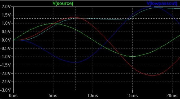
I'm an analog guy by nature, so threw together a circuit in LTSpice. With a 2-pole filter, an inverter, and two summing diode peak detectors, a 50Hz signal is easily detectable by an ADC in 5-8 msec, just over a quarter cycle. The light blue trace is the output of the summed peak detectors. Does take a couple dozen components though.
Capture.JPG

THe difficulty I'm having with digital filters and FFT is troubleshooting, which I suppose can be done by printing variables. To me it's more intuitive to hook up a scope.
 
There are several advantages to using modulation to shift the frequencies of interest to DC, rather than designing a bandpass filter around the each frequency of interest.

With modulation, you can design only one LPF, say with a cutoff of 20 Hz, then you an use it with a sine modulation to effectively get a +/- 20 Hz bandpass filter around any frequency you want to get spectral magnitude measurements. If you want to change the frequency at runtime, you need only recompute the sine table for that frequency, which is easier than sovling filter design equations for different bandpass center frequencies at runtime.

If you need a very tight bandwidth around higher frequencies, you need a very high order filter. With the modulation scheme, you the bandwidth is set by the lowpass filter, and since you shifted the signals of interest down to DC, you can apply a cascade of LPF biquads and downsample to get very tight bandwidths that would be impossible at high frequencies because you don't have option of downsampling several times to ease the filter order requirements, and you can get higher IIR orders while maintaining stability.

If you use a IIR lowpass filter, you will have fairly low processing latency. The audio delay will come from the group delay of the filter, just like an analog filter. If you use a FIR filter, the delay will mostliy from from the sample delay based on the filter order.


Quite an interesting idea...

With a 20Hz lowpass, wouldn't this be anything less than 20 Hz?

Assume your filters are digital. Guess I'm not seeing what the modulation gains over just having a say 45Hz lowpass filter or a Goertzel centered at 40 Hz.


I thought the lower the frequency, the harder (and longer) it is to filter and detect.


With just a filter, there is no repeat... you capture any and all signal energy within the lowpass filter in one shot.

I'm an analog guy by nature, so threw together a circuit in LTSpice. With a 2-pole filter, an inverter, and two summing diode peak detectors, a 50Hz signal is easily detectable by an ADC in 5-8 msec, just over a quarter cycle. The light blue trace is the output of the summed peak detectors. Does take a couple dozen components though.
View attachment 11519

THe difficulty I'm having with digital filters and FFT is troubleshooting, which I suppose can be done by printing variables. To me it's more intuitive to hook up a scope.
 
I do see the advantages now, the ability to quickly and easily change modulation freq. and hence "filter" response.

This part has me a little confused since I haven't done much with IIR or FIR digital filters...
apply a cascade of LPF biquads and downsample to get very tight bandwidths

I thought it was difficult creating any multi-pole low-frequency LP filter, analog or digital.
 
The faster Teensy micros have hardware accelerated DSP instructions through the CMSIS library. Biquad is one of the 2nd order IIR structures they provide. To make a 4th order filter, you put two 2nd order filters in series (cascade), etc. In digital filtering, the higher the sample rate, the higher order you need to get narrow transition bands. With digital audio, when you are only interested in lower frequencies, it takes lower order filters (or fewer cascades) if you are working at lower sample rates. So if you need a lot of attenuation in the stopband, and a very sharp transition band you could do something like:

LP Biquad -> downsample by X -> LP biquad

Downsampling by X=2,4 or even 8 will make the final biquad very effective, whereas without the downsample you would need X times as many biquads for the same effect. You just have to make sure the first LP filter has no significant content above the Nyquist frequency.

So at 44 KHz, if you want to downsample by 2 to 22 KHz, you must first ensure the LP filter removed all frequencies above 11 Khz. If you want to downsample by 4, then you must remove everything above 5.5 KHz, etc.

I do see the advantages now, the ability to quickly and easily change modulation freq. and hence "filter" response.

This part has me a little confused since I haven't done much with IIR or FIR digital filters...


I thought it was difficult creating any multi-pole low-frequency LP filter, analog or digital.
 
Capture and analysis of a 40Hz signal takes at least 1 cycle (25msec) but looking mainly for signal presence, not amplitude accuracy, so hoping to detect an amplitude change in less than a full cycle.
So not FFT.

Sum of squared values for each block can scaled by a window average and compared to a threshold value.

You can catch the front of the envelope as you're not bothered by frequency content but it's supposed to not be very accurate for tempo mapping presumably due to missed beats...
 
Last edited:
Status
Not open for further replies.
Back
Top