Audio project and T3.6.. a lot of problems!

Status
Not open for further replies.

danixdj

Well-known member
Hi, i have the new teensy 3.6 for upgrade my audio project from T3.2 that it haven't free RAM for some new features that i want to add ... so i'm thinking to upgrade to 3.6

BUT.

1. Audio board SGTL-5000 works only if the CPU is <192 Mhz (T3.2 works fine at 144 Mhz and the CPU performance was similar).
Do you know why the audio library don't works up to 192 Mhz? (click and crash!)

2. The EEPROM library does not work with CPU> 180Mhz (crash when i write in the eeprom memory).

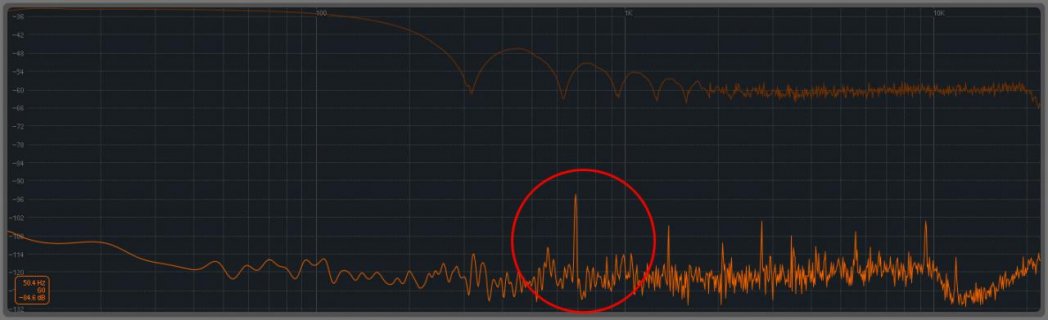
3. Incredible increase of NOISE, there are a lot of noise in input, more and more than a T3.2 (3.2 of OSH are very very silent, and i can not find 3.6 by OSH for now).

so .... there are some solutions for that problems? it's possible to increase RAM for sckatch in T3.2, for me 3.2 is BETTER than 3.6 for now.

Have you some experience in audio project SGTL-5000 and T.3.6?

Thank you ...

Dani
 
I've used it many times with good results, though I tend to stay at the default 180 MHz.

As a quick check, I put a Teensy 3.6 on an audio shield, and set the CPU speed to 192 MHz overclock, and uploaded the WavFilePlayer example. It's playing right now and sounds great on good quality headphones.

DSC_0725_web.jpg

I tested with Arduino 1.8.4 and Teensyduino 1.39 using Linux 64 bit.

Can you give me a little more detail about how I should try to reproduce these problems you're hearing?
 
Hi Paul thank you for the quick reply :)

So .. i works with the line in and out (not mic and not headphones)

This is the noise at 192 Mhz of CPU (if i try up to 192 mhz i have clips and total crash after 4/5 seconds)

[ATTACH = CONFIG] 11522 [/ ATTACH]

headphones disabled


write (CHIP_ANA_POWER, 0x40EF); // power up: lineout, hp, adc, dac

and sgtl5000_1.adcHighPassFilterDisable ();

it's possible to try to total poweoff of mic preamp and all that i don't use in my project? only line in and line out enabled..
 

Attachments

  • npise.jpg
    npise.jpg
    50.1 KB · Views: 117
it's possible to try to total poweoff of mic preamp and all that i don't use in my project? only line in and line out enabled..

Sure, you could mute the headphone and turn the mic gain to zero. The SGTL5000 functions are documented here (right side panel):

https://www.pjrc.com/teensy/gui/?info=AudioControlSGTL5000

This is the noise at 192 Mhz of CPU (if i try up to 192 mhz i have clips and total crash after 4/5 seconds)

If you want me to investigate any further, you need to give me precise step-by-step instructions and all the resources (including the complete code and any files for the SD card) to accurately recreate the problem you're seeing.

For example, that graph is from some instrument or software I don't recognize. It doesn't mean much to me.

As a general rule, I only investigate problems when enough detailed info is posted to reproduce the issue. In this case I made a quick exception to do a quick (and admittedly very simple) listening test with the WavFilePlayer example. At least to my ears it sounds fine. Just to be perfectly clear, that's as much testing as I'm going to do, until you post complete code and all other info needed to recreate the problem.

But I will make one other quick suggestion. Many noise issues turn out to be ground loops. That spike you circled in the graph looks just under 700 Hz, which is very close to the 2nd harmonic of the 344.66 Hz rate the CPU does quite a lot of extra audio DSP work. Maybe the ground current changes more as the CPU runs faster, completing the work in less time and spending the rest of those 2.9 ms doing relatively idle stuff?

Usually this is the quick and easy answer to ground loop problems.

https://www.pjrc.com/store/audio_ground_isolator.html
 
Sure, you could mute the headphone and turn the mic gain to zero. The SGTL5000 functions are documented here (right side panel):

https://www.pjrc.com/teensy/gui/?info=AudioControlSGTL5000


If you want me to investigate any further, you need to give me precise step-by-step instructions and all the resources (including the complete code and any files for the SD card) to accurately recreate the problem you're seeing.

For example, that graph is from some instrument or software I don't recognize. It doesn't mean much to me.

As a general rule, I only investigate problems when enough detailed info is posted to reproduce the issue. In this case I made a quick exception to do a quick (and admittedly very simple) listening test with the WavFilePlayer example. At least to my ears it sounds fine. Just to be perfectly clear, that's as much testing as I'm going to do, until you post complete code and all other info needed to recreate the problem.

But I will make one other quick suggestion. Many noise issues turn out to be ground loops. That spike you circled in the graph looks just under 700 Hz, which is very close to the 2nd harmonic of the 344.66 Hz rate the CPU does quite a lot of extra audio DSP work. Maybe the ground current changes more as the CPU runs faster, completing the work in less time and spending the rest of those 2.9 ms doing relatively idle stuff?

Usually this is the quick and easy answer to ground loop problems.

https://www.pjrc.com/store/audio_ground_isolator.html

The problem is ALWAYS present also wen you haven't a audio object in code... you can connect directly i2s in i2s out and sgtl5000_1.enable(); and you have the noise (and the example code)..

So 2 questions:

Why can't have i2s in i2s out with T3.6 > 192 mhz? crash! (no example code needed, i2s in i2s out directly connected and cpu > 192 mhz).
Why can't write the eeprom when T3.6 > 180 mhz? (it works only for one acces when i try to access for an array or for 2/3 variables the system crash), at 180 Mhz all works fine.

Audio board is connect directly on the top of the teensy by solder pins.. (0.5cm of distance)

Why i haven't that problems with T3.2? no noise, eeprom ok?

Connections are identical, and the same position (on the top)..

I can't do anythings that i can do with T3.2, i need more RAM memory only and now i have ram but a lot of problems :(

Your suggestion from pjrc store is not a solution for me, i must to do it from a circuit, can't use the jack connection in my project... i hope to solve without the others components with a mod of existent...
 
for the eeprom problem... at 192 mhz

EEPROM.put (3980, var1); EEPROM.put (3990, var2); -> CRASH

EEPROM.put (3980, var1); delay(300); EEPROM.put (3990, var2); -> WORKS

but... in an audio project i can't use the delay... and i have more data to store... it's impossible to do...
 
without input and output cables connected the rms (using rms object) have 0.0096 of the noise... without input, without output :( T.3.2 0.0042
 
for the eeprom problem... at 192 mhz

EEPROM.put (3980, var1); EEPROM.put (3990, var2); -> CRASH

EEPROM.put (3980, var1); delay(300); EEPROM.put (3990, var2); -> WORKS

but... in an audio project i can't use the delay... and i have more data to store... it's impossible to do...

and if i have an array

preset memory = {
var1, var2, var3, var4,
var5, var6, var7, var8, var9, var10, var11,
var12, var13, var14, var15, var16, var17, var18, var19, var20, var21, var22, var23, var24, var25, var26
};


EEPROM.put( 0, memory );

-> CRASH!
 
I just don't know how I can try to say this more clearly... I'm not going to look at this unless you post a complete program I can copy and paste into Arduino. I already set up hardware and made a guess for you. That's it, not again. Even if it's trivial, even if it's only a minor change to one of the examples, you need to post a full program I can copy and paste into Arduino and run on a Teensy board.

Edit: Look, I'm not trying to deny there's a bug. There very likely is a bug. Or if not a bug, maybe a misunderstanding, or wrong documentation. But it could be a bug. Especially at 192 MHz overclock, not much testing has been done.
 
I just don't know how I can try to say this more clearly... I'm not going to look at this unless you post a complete program I can copy and paste into Arduino. I already set up hardware and made a guess for you. That's it, not again. Even if it's trivial, even if it's only a minor change to one of the examples, you need to post a full program I can copy and paste into Arduino and run on a Teensy board.

Ok, this is for AUDIO BOARD SGTL-5000 and T3.6 240 Mhz, arduino 1.83 , teensyduino 1.38, faster -> Click and CRASH!

let me know, thank you..


Code:
#include <Audio.h>
#include <Wire.h>
#include <SPI.h>
#include <SD.h>
#include <SerialFlash.h>

// GUItool: begin automatically generated code
AudioInputI2S            i2s1;           //xy=98,67
AudioOutputI2S           i2s2;           //xy=1009,88
AudioConnection          patchCord1(i2s1, 0, i2s2, 0);
AudioConnection          patchCord2(i2s1, 1, i2s2, 1);
AudioControlSGTL5000     sgtl5000_1;     //xy=172,201
// GUItool: end automatically generated code

void setup() {
sgtl5000_1.enable();
AudioMemory(40);
sgtl5000_1.lineOutLevel(13);
sgtl5000_1.lineInLevel(0);
sgtl5000_1.adcHighPassFilterDisable();
sgtl5000_1.muteHeadphone();
}

void loop() {
}


audio of the clips https://www.dropbox.com/s/12l0m1cdrgompma/240mhz.mp3?dl=0


And you can listen the problem of noise in the same code, it's ALWAYS present..
 
I'm running it here.

DSC_0726_web.jpg

I definitely hear artifacts in the audio when running at 240 MHz, which I don't hear with 180 MHz.

At 216 MHz the artifacts sound even worst, and after a minute or two the audio does stop. But the processor doesn't seem to be crashed. I added this in loop:

Code:
void loop() {
  static int count=0;
  Serial.printf("count=%d\n", count++);
  delay(500);
}

It's still printing the number to the Arduino Serial Monitor after the audio stops.

Running at 192 MHz seems to work properly. I can't hear any artifacts. Sounds the same as with 180 MHz.
 
I'm running it here.

View attachment 11523

I definitely hear artifacts in the audio when running at 240 MHz, which I don't hear with 180 MHz.

At 216 MHz the artifacts sound even worst, and after a minute or two the audio does stop. But the processor doesn't seem to be crashed. I added this in loop:

Code:
void loop() {
  static int count=0;
  Serial.printf("count=%d\n", count++);
  delay(500);
}

It's still printing the number to the Arduino Serial Monitor after the audio stops.

Running at 192 MHz seems to work properly. I can't hear any artifacts. Sounds the same as with 180 MHz.

I know that it works if the CPU is <= 192 mhz... but i hope than it's possibile to have a more fast CPU clock in the future..

so... for CPU there aren't solutions, for the noise... ?! In T3.2 there isn't noise with the same configuration... also for this there aren't solutions?

i write a test code for the eeprom problem when the cpu > 180mhz... but for now if there aren't solutions for these 2 big problems (noise always at all CPU freq, and cpu clock must to be <192 mhz) T3.6 can't be used for a good quality audio project.

T3.2 is the best way for now, great sound quality but slow CPU and ram limitations...
 
Sadly, it seems the fractional clock divider for MCLK just isn't able to run reliably at 216 or 240 MHz. Remember, this is pretty substantial overclocking, and the first thing that circuit does is effectively double the clock by triggering on both the rising and falling edges (at least that's how I imaging Freescale designed it) so it's basically running a digital counter at *double* the clock speed.

Unfortunately there's only 3 choices for input to the MCLK generator, either the system clock, the 16 MHz crystal, or the special clock mux configured by SIM_SOPT2. But 4 of the SIM_SOPT2 choices are low accuracy RC oscillators, one if the PLL so it's the same as the system clock. That leaves one more possibility, from the USB1 port.

Maybe it'd be possible to configure the USB1 PHY to generate a special clock for the IS2 MCLK. Maybe? But I'm probably not going to work on this. If you or anyone else whats to try, help yourself to the USBHost_t36 library code which initializes the USB1 PHY. That's probably most of the work to get it running, then hopefully just write to some of its registers to configure and turn on PFDCLK. Of course configure SIM_SOPT2 to pass USB1PFDCLK, and edit the I2S code to use that for MCLK, and of course set the fractional divider numerator and denominator to get 11.29 MHz from whatever clock you managed to create for USB1PFDCLK.

Edit: if anyone get this working at 216 or 240 MHz, please send a pull request.....
 
On the noise you're hearing, can you try running at only 120 MHz?

The K66 chip on Teensy 3.6 has a special HSRUN mode which basically increases the internal voltage inside the chip, so it'll run faster. This setting is only used for speeds over 120 MHz. Maybe it will make a different for the noise problem you're hearing?

Nothing changed.. :(
 
Paul... i think that the problem is about SPI communication... if i add a AudioEffectDelayExternal object the noise increase, if don't use this object or if i use AudioEffectDelay (not external) the noise is low...

Any idea?
 
i'm testing T.3.6 180 mhz (F_BUS 90000000) faster

if i increase SPI clock (#define SPISETTING SPISettings(48000000, MSBFIRST, SPI_MODE0) in effect_delay_ext.cpp) the noise goes from -84db to -96 db


At 180 Mhz i haven't problem to write in eeprom, i2s is ok and now with this SPI clock mode the cpu usage is -20%


If someone have a suggestion for noise (isn't acceptable but better than before) please let me know...
 
As I said earlier, I'm pretty sure you're seeing the effects of currents related to the digital logic flowing through the analog grounds connecting your signals. An extra chip and the rapid switching of the SPI pins will add extra digital current.

You may not agree, but you did ask "Any idea?".
 
As I said earlier, I'm pretty sure you're seeing the effects of currents related to the digital logic flowing through the analog grounds connecting your signals. An extra chip and the rapid switching of the SPI pins will add extra digital current.

You may not agree, but you did ask "Any idea?".

What can i do?
 
Status
Not open for further replies.
Back
Top