While working on my first project (a basic 2-way MIDI DAW Controller) , more specifically on rotary encoders with LED Rings around them, I noticed how much of a pain it was to wire it on perfboard, especially since I don't want a huge footprint. After finding out about the relatively low price of getting small PCBs made , even at small quantities, I figured I'd be better off designing a PCB with some SMD parts for something like this.
However, my general electronics knowledge is still very limited, and as you may have guessed, this would be my first PCB design, so I also have a few basic questions.
As far as the led ring goes, what I'd like to achieve is this (starting with highest priority)
-chainable (let's say up to 8 or preferably 16 times)
-fewest amount of board to board connections/connectors/ used teensy pins
-easy possibility to control brightness, preferably in software (doesn't have to be every LED separately but should be every board separately). And in case it matters for PWM or related stuff: The brightness setting doesn't have to be high-resolution, 16 steps would be enough.
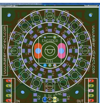
Here's what I have so far:
https://imgur.com/a/mmKmO
The connector wires got all tangled up after moving the components around, so I just deleted them, but the idea would be 2 connectors, IN and OUT that each have 3V,GND, and the 3 lines for the shift register (data, clock , refresh). The rotary encoder (with switch) part of the schematic will see some hardware debouncing added and go to a separate 3 pin output connector (Rotary Encoder A+B, Switch). The 3V line will probably come from an external power supply.
Here are the questions that come to mind:
- Am I missing something in the LED Ring part of the schematic? I honestly have little idea when or where to put extra capacitors or resistors that might be needed.
- This schematic seems to be pretty bad for my 3rd requirement, I think PWM-ing even 4 encoder rings (64 LED) would be terribly inefficient. Also I can't help but wonder if 16 separate resistors are really needed here.
Knowing the MAX7219/7221, it would be nice to have a similar setup with a common current-limiting resistor, if only to make it easier to change the brightness through hardware / replacing one resistor instead of 16. However at 10x the price of two 595 shift registers the 7219 seems a bit overkill ? Of course I could use them to control four 16-LED-rings, but if there's a solution that is more modular (enabling me to add "self-contained" modules one by one , rather than having a chip control 4 modules ), I would much prefer that.
Thanks for reading and best regards,
Jazz
However, my general electronics knowledge is still very limited, and as you may have guessed, this would be my first PCB design, so I also have a few basic questions.
As far as the led ring goes, what I'd like to achieve is this (starting with highest priority)
-chainable (let's say up to 8 or preferably 16 times)
-fewest amount of board to board connections/connectors/ used teensy pins
-easy possibility to control brightness, preferably in software (doesn't have to be every LED separately but should be every board separately). And in case it matters for PWM or related stuff: The brightness setting doesn't have to be high-resolution, 16 steps would be enough.
Here's what I have so far:
https://imgur.com/a/mmKmO
The connector wires got all tangled up after moving the components around, so I just deleted them, but the idea would be 2 connectors, IN and OUT that each have 3V,GND, and the 3 lines for the shift register (data, clock , refresh). The rotary encoder (with switch) part of the schematic will see some hardware debouncing added and go to a separate 3 pin output connector (Rotary Encoder A+B, Switch). The 3V line will probably come from an external power supply.
Here are the questions that come to mind:
- Am I missing something in the LED Ring part of the schematic? I honestly have little idea when or where to put extra capacitors or resistors that might be needed.
- This schematic seems to be pretty bad for my 3rd requirement, I think PWM-ing even 4 encoder rings (64 LED) would be terribly inefficient. Also I can't help but wonder if 16 separate resistors are really needed here.
Knowing the MAX7219/7221, it would be nice to have a similar setup with a common current-limiting resistor, if only to make it easier to change the brightness through hardware / replacing one resistor instead of 16. However at 10x the price of two 595 shift registers the 7219 seems a bit overkill ? Of course I could use them to control four 16-LED-rings, but if there's a solution that is more modular (enabling me to add "self-contained" modules one by one , rather than having a chip control 4 modules ), I would much prefer that.
Thanks for reading and best regards,
Jazz
")