Teensy 3.6 SPI transaction speed problem

Status
Not open for further replies.

Abadi alali

Active member
Hello,

I am using teensy 3.6 to interface with the LTC2315-12 ADC demo board. The ADC can reach 5 MSPS if the clock (SCK) is 87.7 MHz.

I was able to make the ADC work but for a maximum of 500 kSPS with SCK = 16 MHz, the problem I am facing that the transaction (from SPI.beginTransaction to endTransaction) is taking around 2 microseconds which is too much for my application. as you can see from my attached code (the part that has the SPI reading only)

this code works for any any t>=2 (which gives me a perfect readings with sampling rate of 1/t but when I try t=1 the code doesn't return done and it hangs after inspecting it I saw that the ADCRead function takes 2 microseconds or more to get a single read and when I try t=1 the interrupt is trigerring in the middle of an SPI read. So is this a limitation of the teensy 3.6 and this is the fastest transaction it can make or is there soemthign wrong I am doing also what are the other ways of doing this other than the interval timer?

Thanks a lot in advance :D


Code:
#include <SPI.h> 
IntervalTimer myTimer;
const int slaveAPin = 20;
SPISettings settingsA(8000000, MSBFIRST, SPI_MODE0); 
SPISettings settingsB(16000000, MSBFIRST, SPI_MODE0);
volatile unsigned long Count = 0;

void ADCRead(void) {

if (t>3)
      SPI.beginTransaction(settingsA);
if (t<= 3){
      SPI.beginTransaction(settingsB); 
}
    digitalWriteFast (slaveAPin, LOW);
    SPI0_SR = SPI_SR_TCF;
    SPI0_PUSHR = 0 | SPI_PUSHR_CTAS(1);
    while (!(SPI0_SR & SPI_SR_TCF)) ; // wait
    values[blinkCount]=SPI0_POPR;  
    digitalWriteFast (slaveAPin, HIGH);
    SPI.endTransaction();

    Count = Count + 1;  // increase when LED ture
}

void main ()
{

 if (Serial.available()) {
    int c = Serial.read();

if (c =='S'){
        t = Serial.parseInt();

      Count=0;  interrupts(); myTimer.begin(ADCRead, t);
     while(blinkCount <=1024);
      if (Count >= 1024)
 {

noInterrupts();
myTimer.end();

 }
 
   else
{

   interrupts();

}

Serial.print("done");
}

 if (c == 'Q')
    {
      for(int i=1;i<=1024;i++)
      {
        Serial.print(i);
        Serial.print(" , ");

        Serial.println(values[i]);
      }
    }

}

}
 
If that's the only SPI device, just don't use transactions. Or start the transcation in setup() and never stop it. And, you can use a faster spi-speed (max F_BUS/2).
 
No problem, if both work with the same SPI-Speed and have the same spi-mode.
Edit: I'm transfering some MB/sec to a Display. No problem.
 
No problem, if both work with the same SPI-Speed and have the same spi-mode.
Edit: I'm transfering some MB/sec to a Display. No problem.

it is still not working and the transaction takes around 2 micro seconds
I mean this portion

digitalWriteFast (slaveAPin, LOW);
SPI0_SR = SPI_SR_TCF;
SPI0_PUSHR = 0 | SPI_PUSHR_CTAS(1);
while (!(SPI0_SR & SPI_SR_TCF)) ; // wait
values[blinkCount]=SPI0_POPR;
digitalWriteFast (slaveAPin, HIGH);
 
I guess the real question is what is your requirement for your device? Do you need the CS pin to be selected/deselected per sample?

Also your code uses the SPI in about the same way as if you simply used SPI.transfer(0); That is it puts out one byte on the SPI output queue, and then waits until that byte has been shifted it... At 8mhz that would take at least 1us to transfer the byte out... Plus you add onto this the time to do your digital writes and put stuff in queue......

Now If your CS pin is one of the hardware CS pins, you can encode that the CS pin should be on during that transfer.
That is you can call pinIsChipSelect to verify if a pin is a CS pin, and then you can use setCS to convert the pin To an SPI CS pin and get the bitmask back for what pin to select... Suppose you save that in a variable like: pcs;

If you then do: SPI0_PUSHR = 0 | SPI_PUSHR_CTAS(1) | pcs;

Would do the Chip select as part of the PUSHR... If you needed the Chip select to continue through multiple byte/word transfers, you would also include the SPI_PUSHR_CONT flag as part of the PUSHR...

But even with this you are still in lock step, neutering the SPI, where you can not start a transfer until you completed the previous one...
You could in many cases, do several PUSHR instructions to fill the queue and then check for how many entries are in the POPR queue and pop those off as they become available...

For more information on how to do this, look at the SPI library at some of the transfer functions, like:
transfer(txBuf, rxBuf, cnt)...
 
Actually, in my case the CS pin is what triggers the ADC to sample, and then the SPI should read 2 Bytes. I tried to use setCS but it doesn't work and it was mentioned ( setCS() is a special function, not intended for use from normal Arduino programs/sketches)!!
Also, you mentioned that it would take 1us if the clock was 8 MHz but in my case even when I am tying a higher clock and removing the digitalfastwrite it is still taking around 2us for 2 Bytes.
 
Actually neither is PUSHR/POPR used for normal programs... They use transfer and transfer16....

However if you wish to go at the register level, then you should have the Reference PDF in front of you to see that the CS Mask is shifted up 16 bits...

So if you have a simple program like:
Code:
#define USE_SPI_CS

#include <SPI.h>
const int slaveAPin = 20;
uint32_t csMASK;
uint16_t blinkCount;
SPISettings settingsB(16000000, MSBFIRST, SPI_MODE0);
SPISettings settingsA(8000000, MSBFIRST, SPI_MODE0);
#define SAMPLE_COUNT 50
uint16_t values[SAMPLE_COUNT];
void setup() {
  while (!Serial && (millis() < 2000)) ;

  Serial.begin(115200);

  SPI.begin();
#ifdef USE_SPI_CS
  csMASK = SPI.setCS(slaveAPin) << 16;
  Serial.printf("CS Mask: %x\n", csMASK);
#else
  pinMode(slaveAPin, OUTPUT);
  digitalWriteFast(slaveAPin, HIGH);
#endif  
}

void loop() {
  SPI.beginTransaction(settingsB);
  blinkCount = 0;
  uint32_t ulStart = micros();
  for (auto i = 0; i < SAMPLE_COUNT; i++) {
    ADCRead();
  }
  uint32_t dt = micros() - ulStart;
  Serial.println(dt, HEX);
  SPI.endTransaction();

  delay(500);
}


#ifdef USE_SPI_CS
void ADCRead(void) {

  SPI0_SR = SPI_SR_TCF;
  SPI0_PUSHR = 0 | SPI_PUSHR_CTAS(1) | csMASK;
  while (!(SPI0_SR & SPI_SR_TCF)) ; // wait
  values[blinkCount++] = SPI0_POPR;
}
#else
void ADCRead(void) {


  digitalWriteFast(slaveAPin, LOW);
  SPI0_SR = SPI_SR_TCF;
  SPI0_PUSHR = 0 | SPI_PUSHR_CTAS(1) | SPI_PUSHR_CONT;
  while (!(SPI0_SR & SPI_SR_TCF)) ; // wait
  digitalWriteFast(slaveAPin, HIGH);
  values[blinkCount++] = SPI0_POPR;
}
#endif

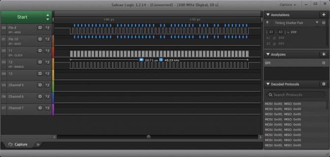
I am doing the 50 samples in about 64.77us...
screenshot.jpg

Note in this case I am not sure if the encoding of SPI cs is helping or not... The issue is there are timings built into SPI for delays before and CS pins are asserted/deasserted which you can configure some...

I actually show two ways... Without using the CS, but telling SPI to do a continue operation (does not do delays builtin)... Both timings pretty close.
But with CS encoded 1.3us per sample... using _CONT and digitalWriteFast... about 1.33...
 
Thanks alot for making it clearer, but as I mentioned before I am interested in much lower time per sample and I want to use a higher clock to achieve 5 MSPS which is around 0.2us per sample. I am not even able to get 1 MSPS which is 1us even after seting the sck to values > 24 MHz. Is that not possible with the teensy 3.6 or am I doing something wrong.
 
That is not likely to work.

If my math is correct, the highest SPI speed you can get is 60mhz. You can get this by running at 240mhz, plus edit Kinetisk.h to change the F_BUS speed to 120mhz instead of default 60mhz.
Now SPI can run at F_BUS/2 so you can set the max to 60mhz.

Now remember you are outputting 16 bits per item. so Max speed is 3.75M samples per second assuming no overhead. With that setup I was seeing the 50 samples maybe taking 20.7us so getting closer.

screenshot.jpg

You might be able to get even closer if you don't lock step your code, and use the queues. That is you can have your code:
Continue to push stuff onto the stack until the queue is full, and during your looping check to see if any items are on the POPR queue and pop those off. With the last item maybe push it on with the EOQF flag or the like and detect that at the end waiting for the last POPR registers to be returned... This in theory should cut down some overhead and allow the SPI to continue to do transfers when you are doing your bookkeeping...

There are examples of code that do this, like the SPI library... Look at the transfer(buf, retbuf, cnt) function or look at ILI9341_t3 library. There are helper functions in the header file for pushing things on stack and checking for full, waiting until not full, waiting until complete...
 
I did some quick hacking to output the 50 bytes the way I mentioned borrowing code from ili9341_t3 library. Note: it is wrong as the macros I used throw away the POPR data instead of saving it...
But that should not impact the timings...

So with that the timing went from 20.7us for the 50 down to 15.4...

The section of hacked up code looked like... Again the better example of doing this is the SPI library...
Code:
inline void waitTransmitComplete(void) {
  uint32_t tmp __attribute__((unused));
  while (!(KINETISK_SPI0.SR & SPI_SR_TCF)) ; // wait until final output done
  tmp = KINETISK_SPI0.POPR;                  // drain the final RX FIFO word
}
inline void waitTransmitComplete(uint32_t mcr) {
  uint32_t tmp __attribute__((unused));
  while (1) {
    uint32_t sr = KINETISK_SPI0.SR;
    if (sr & SPI_SR_EOQF) break;  // wait for last transmit
    if (sr &  0xF0) tmp = KINETISK_SPI0.POPR;
  }
  KINETISK_SPI0.SR = SPI_SR_EOQF;
  SPI0_MCR = mcr;
  while (KINETISK_SPI0.SR & 0xF0) {
    tmp = KINETISK_SPI0.POPR;
  }
}

inline void waitFifoNotFull(void) {
  uint32_t sr;
  uint32_t tmp __attribute__((unused));
  do {
    sr = KINETISK_SPI0.SR;
    if (sr & 0xF0) tmp = KINETISK_SPI0.POPR;  // drain RX FIFO
  } while ((sr & (15 << 12)) > (3 << 12));
}

void ADCReadN(uint16_t count) {
  while (count-- > 1) {
    SPI0_PUSHR = 0 | SPI_PUSHR_CTAS(1) | csMASK;
    waitFifoNotFull();
  }
  uint32_t mcr = SPI0_MCR;
  KINETISK_SPI0.PUSHR = 0 | csMASK | SPI_PUSHR_CTAS(1) | SPI_PUSHR_EOQ;
  waitTransmitComplete(mcr);


}
 
Thank you so much and sorry for asking a lot but my programming skills are limited when it comes to using the registers and stuff like that.

I tried the transfer function you mentioned and it is still taking too much time I guess 1.3us like the previous one. Now I was trying the code you wrote in your last comment but I am not sure why I am not getting the right read from it, where exactly should I save the readed value (16 bit) previously I was simply taknig the value out of the SPI0_POPR but now there are multiple functions with the SPI0.POPR so I am a bit confused.

One last thing in my case since I want to achieve a high sampling rate and I need SCK to be 87.9 MHz is there any way of using an external clock for that and program the controller to follow the falling edge of that controller to read the MISO data?!
 
Status
Not open for further replies.
Back
Top