My project the data logger. need help

Lukashuk

Well-known member
Hello, dear forum users!
Forgive me for my bad English, I use Google as a translator.
I plan to make the data logger, paralel 8 bits + 1 clock + 1 start frame. capture speed of 25.6 kHz. recording time 5 minutes. i need to write on SD card.
Question 1 and the most important: Teensy3.2 will be able to cope with this task? or do I need to look for a more powerful solution?
If there is a positive answer to 1 question then, I have no doubt that there will be more questions.
Maybe I need Teensy3.6? then i have to wait for the parcel from the Internet
Thank you for attention.
 
Last edited:
Welcome

Teensy3.2 can read 10 bits much faster than 25.6khz, one input takes a couple of clock cycles at 96mhz if the pin to be read is constant - for(i=0;i<10;i++) digitalRead(i) is slower

Simultaneous read is harder code but is possible, you can read all pins on a port (PTx)
https://www.pjrc.com/teensy/schematic.html
Port C - pins labelled PTCx may work for you

Writing to SD card at that rate may be more complex and require buffering for efficient writes - this will need code that can keep reading while SD card is writing.
 
Thank you for responding. I looked at the diagram and see that parallel data-8 bits can only be read on port D, because a memory card is connected to port C.
Yes, I understand that I have to make two buffers, while 1 writes to the card 2 writes the parallel port, and at the right time toggle the buffers.
Also I need an external interrupt in order for the new byte to come.

I'm talking for now only about Teensy3.2 because he is in my city and does not need to order on the Internet for Teensy3.6
 
Yes, Teensy 3.2 should be fast enough.

As a simple comparison, the audio example from File > Examples > Audio > Recorder is able to write 16 bit audio data at 44100 Hz to the SD card. So your application of 8 bit data at 25600 Hz only about 1/4 of that speed.

You will need to buffer enough data in RAM to deal with the SD card latency. The audio library "queue" objects do that you for. Obviously you'll need to write code to grab the incoming data and buffer it. At only 25.6 kHz, you can probably just run an interrupt. It will burn quite a bit of CPU time, but the rate is slow enough that it will probably work. Triggering a DMA channel which reads the GPIO register would be much more efficient.
 
Thank you for giving me hope!
I will study a lot, This topic is new for me, especially the DMA channel launch, which reads the GPIO register.
Where can I read about this?

I will train on 3.2, but 3.6 today I bought in an online store.
Thanks again.
 
Welcome

Teensy3.2 can read 10 bits much faster than 25.6khz, one input takes a couple of clock cycles at 96mhz if the pin to be read is constant - for(i=0;i<10;i++) digitalRead(i) is slower

Simultaneous read is harder code but is possible, you can read all pins on a port (PTx)
https://www.pjrc.com/teensy/schematic.html
Port C - pins labelled PTCx may work for you

Writing to SD card at that rate may be more complex and require buffering for efficient writes - this will need code that can keep reading while SD card is writing.
I tried to analyze the circuit and it looks like GremlinWrangler was right
I really can use the PortC, I have to assign the SPI pins to PortD? I have not yet figured out how to connect the SD card to 3.6. Where can I find the 3.6 circuit? I want it to be interchangeable without fixing the code, or with minor fixes.
 
Teensy 3.6 has an onboard SD card slot that uses dedicated pins. You can still use an external card same as 3.2 if common design is a goal but main advantage of the 3.6 for you beyond the slightly faster CPU is the hardware accelerated SD card.
 
In 3.6, is the card connected to other ports? and does not touch port C or D?
Where can I see the scheme 3.6?
 
T_3.6 SD socket is wired to unique pins exclusive of all other bus associations. Schematics at PJRC.com to confirm the ports.
 
I first make a signal generator for parallel data.
Here is the code for Arduino Mega.
But Mega has a 5-volt outlet,
How to translate this code to Aduino Due?

Code:
byte MyByte =0;
int i=0;
void setup() 
{
DDRB = 1<<7;  //Arduino pin 13 - clock for data
DDRC  = B11111111 ;//output
PORTC = B00000000 ;// data
}
void loop() 
{ //period 100 mkSec = 10 kGz  after increase the speed
  for(i=0; i<=255; i++)
  {
    MyByte++;
    PORTC = MyByte;
    delayMicroseconds(5);
    PORTB = 1<<7;
    delayMicroseconds(85);         
    PORTB = 0<<7;
    delayMicroseconds(10); 
  }
}
 
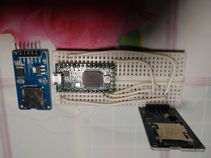
T3_2.jpg
I'm trying to run examples with a SD card on 3.2 ,,
I tried 2 different cards and 2 different adapters, I get different errors

Code:
[CODE]Can't access SD card. Do not reformat.
SD errorCode: 0X43,0XFF
No card, wrong chip select pin, or SPI problem?
SD errorCode: 0X20,0XFF
[/CODE]

what could be wrong?
on T2 ++ all cards and adapters work

Im used SdFat and SD
I checked the voltage on the adapter after the converter 2.28v

Oh, I got started, I also connected to 5,
I do not know what happened, I spent 4 hours
Its OK!

only 72MHz works
 
Last edited:
for my project I decided to make a test generator.
Here is the program code

Code:
 #define write8inline(d) { \
   PORTD = (GPIOD_PDOR & B00000000) | ((d) & B11111111); \
   }
  #define read8inline() ( (GPIOD_PDIR & B11111111))
  #define setWriteDirInline() { \
    pinMode(2, OUTPUT); \
    pinMode(14, OUTPUT); \
    pinMode(7, OUTPUT); \
    pinMode(8, OUTPUT); \
    pinMode(6, OUTPUT); \
    pinMode(20, OUTPUT); \
    pinMode(21, OUTPUT); \
    pinMode(5, OUTPUT); }
  #define setReadDirInline() { \
    pinMode(2, INPUT); \
    pinMode(14, INPUT); \
    pinMode(7, INPUT); \
    pinMode(8, INPUT); \
    pinMode(6, INPUT); \
    pinMode(20, INPUT); \
    pinMode(21, INPUT); \
    pinMode(5, INPUT); }
    
#define write8 write8inline

//  to access any byte int or long
#define LOBYTE(x) (*(unsigned char*)&x)       // low byte
#define HIBYTE(x) (*(((unsigned char*)&x)+1)) // 2
#define BYTE3(x) (*(((unsigned char*)&x)+2))  // 3
#define BYTE4(x) (*(((unsigned char*)&x)+3))  // 4 


const PROGMEM byte tab_sin[256] =
{ 
  0x7E, 0x7B, 0x78, 0x75, 0x72, 0x6F, 0x6C, 0x69, 0x66, 0x63, 0x60, 0x5D, 0x5A, 0x57, 0x54, 0x51, 
  0x4E, 0x4B, 0x48, 0x45, 0x43, 0x40, 0x3D, 0x3B, 0x38, 0x35, 0x33, 0x30, 0x2E, 0x2C, 0x29, 0x27, 
  0x25, 0x23, 0x20, 0x1E, 0x1C, 0x1A, 0x18, 0x17, 0x15, 0x13, 0x12, 0x10, 0x0E, 0x0D, 0x0C, 0x0A,
  0x09, 0x08, 0x07, 0x06, 0x05, 0x04, 0x03, 0x03, 0x02, 0x01, 0x01, 0x00, 0x00, 0x00, 0x00, 0x00,
  0x00, 0x00, 0x00, 0x00, 0x00, 0x00, 0x01, 0x01, 0x02, 0x03, 0x03, 0x04, 0x05, 0x06, 0x07, 0x08,
  0x09, 0x0A, 0x0C, 0x0D, 0x0E, 0x10, 0x12, 0x13, 0x15, 0x17, 0x18, 0x1A, 0x1C, 0x1E, 0x20, 0x23,
  0x25, 0x27, 0x29, 0x2C, 0x2E, 0x30, 0x33, 0x35, 0x38, 0x3B, 0x3D, 0x40, 0x43, 0x45, 0x48, 0x4B, 
  0x4E, 0x51, 0x54, 0x57, 0x5A, 0x5D, 0x60, 0x63, 0x66, 0x69, 0x6C, 0x6F, 0x72, 0x75, 0x78, 0x7B, 
  0x7E, 0x82, 0x85, 0x88, 0x8B, 0x8E, 0x91, 0x94, 0x97, 0x9A, 0x9D, 0xA0, 0xA3, 0xA6, 0xA9, 0xAC,
  0xAF, 0xB2, 0xB5, 0xB8, 0xBA, 0xBD, 0xC0, 0xC2, 0xC5, 0xC8, 0xCA, 0xCD, 0xCF, 0xD1, 0xD4, 0xD6,
  0xD8, 0xDA, 0xDD, 0xDF, 0xE1, 0xE3, 0xE5, 0xE6, 0xE8, 0xEA, 0xEB, 0xED, 0xEF, 0xF0, 0xF1, 0xF3,
  0xF4, 0xF5, 0xF6, 0xF7, 0xF8, 0xF9, 0xFA, 0xFA, 0xFB, 0xFC, 0xFC, 0xFD, 0xFD, 0xFD, 0xFD, 0xFD,
  0xFE, 0xFD, 0xFD, 0xFD, 0xFD, 0xFD, 0xFC, 0xFC, 0xFB, 0xFA, 0xFA, 0xF9, 0xF8, 0xF7, 0xF6, 0xF5,
  0xF4, 0xF3, 0xF1, 0xF0, 0xEF, 0xED, 0xEB, 0xEA, 0xE8, 0xE6, 0xE5, 0xE3, 0xE1, 0xDF, 0xDD, 0xDA,
  0xD8, 0xD6, 0xD4, 0xD1, 0xCF, 0xCD, 0xCA, 0xC8, 0xC5, 0xC2, 0xC0, 0xBD, 0xBA, 0xB8, 0xB5, 0xB2,
  0xAF, 0xAC, 0xA9, 0xA6, 0xA3, 0xA0, 0x9D, 0x9A, 0x97, 0x94, 0x91, 0x8E, 0x8B, 0x88, 0x85, 0x82 
};
#define clocks 15    //15 pin Teensy3.2 - PORTC0 - signal clock for byte readiness
#define frame  16    //16 pin Teensy3.2 - PORTB0 - start of frame
#define stop_rec 17  //17 pin Teensy3.2 - PORTB1 - finish the recording and close the file
#define led 13
uint32_t max_byte=0;//The device should not work more than 5 minutes. During this time 76800000 bytes will be stored  
uint8_t pointer0sin;//does nothing, for the same synchronization length
uint8_t pointer1sin=0;//0 degres;
uint8_t pointer2sin=32;//45 degres;
uint8_t pointer3sin=64;//90
uint8_t pointer4sin=128;//180
uint8_t my9_byte=0;// 9 byte - 8 bit saw
uint8_t my10_byte=0;// 10 byte - status bits

#define myDelay 3

void setup() 
{
  pinMode(led, OUTPUT);
  pinMode(clocks, OUTPUT);
  pinMode(frame, OUTPUT);
  pinMode(stop_rec, OUTPUT);
  
  pinMode(2, OUTPUT);//D0 
  pinMode(14, OUTPUT); //D1
  pinMode(7, OUTPUT);//D2
  pinMode(8, OUTPUT);//D3
  pinMode(6, OUTPUT);//D4
  pinMode(20, OUTPUT);//D5
  pinMode(21, OUTPUT);//D6
  pinMode(5, OUTPUT); //D7
}
void loop() 
{
  while(1) 
  { 
//Sine wave 1   
//high byte write 
    GPIOD_PDOR=tab_sin[pointer1sin];// high byte of value    
    digitalWriteFast(frame, HIGH);// beginning of frame  
    digitalWriteFast(clocks, HIGH);// synchronization     
    delayMicroseconds(myDelay);
    digitalWriteFast(clocks, LOW);// synchronization
    pointer0sin++;//does nothing, for the same synchronization length
//low byte write    
    GPIOD_PDOR=tab_sin[pointer1sin];// high byte of value    
    digitalWriteFast(frame, LOW);// within a frame 
    digitalWriteFast(clocks, HIGH);// synchronization     
    delayMicroseconds(myDelay);
    digitalWriteFast(clocks, LOW);// synchronization
    pointer1sin++;
//Sine wave 2   
//high byte write    
    GPIOD_PDOR=tab_sin[pointer2sin];//GPIOD_PDOR=0;// high byte of value
    digitalWriteFast(frame, LOW);// if not start frame this bit =0
    digitalWriteFast(clocks, HIGH);// synchronization     
    delayMicroseconds(myDelay);
    digitalWriteFast(clocks, LOW);// synchronization
    pointer0sin++;//does nothing, for the same synchronization length
//low byte write    
    GPIOD_PDOR=tab_sin[pointer2sin];// low byte of value    
    digitalWriteFast(frame, LOW);// within a frame 
    digitalWriteFast(clocks, HIGH);// synchronization     
    delayMicroseconds(myDelay);
    digitalWriteFast(clocks, LOW);// synchronization
    pointer2sin++;
//Sine wave 3   
//high byte write     
    GPIOD_PDOR=tab_sin[pointer3sin];//GPIOD_PDOR=0;// high byte of value    
    digitalWriteFast(frame, LOW);// if not start frame this bit =0
    digitalWriteFast(clocks, HIGH);// synchronization     
    delayMicroseconds(myDelay);
    digitalWriteFast(clocks, LOW);// synchronization
    pointer0sin++;//does nothing, for the same synchronization length
//low byte write    
    GPIOD_PDOR=tab_sin[pointer3sin];// high byte of value   
    digitalWriteFast(frame, LOW);// within a frame 
    digitalWriteFast(clocks, HIGH);// synchronization     
    delayMicroseconds(myDelay);
    digitalWriteFast(clocks, LOW);// synchronization
    pointer3sin++;
//Sine wave 4   
//high byte write     
    GPIOD_PDOR=tab_sin[pointer4sin];// GPIOD_PDOR=0;// high byte of value    
    digitalWriteFast(frame, LOW);// if not start frame this bit =0
    digitalWriteFast(clocks, HIGH);// synchronization     
    delayMicroseconds(myDelay);
    digitalWriteFast(clocks, LOW);// synchronization
    pointer0sin++;//does nothing, for the same synchronization length
//low byte write    
    GPIOD_PDOR=tab_sin[pointer4sin];// high byte of value   
    digitalWriteFast(frame, LOW);// within a frame 
    digitalWriteFast(clocks, HIGH);// synchronization     
    delayMicroseconds(myDelay);
    digitalWriteFast(clocks, LOW);// synchronization
    pointer4sin++;
    
//9 and 10 byte   
//9 byte write 
        
    GPIOD_PDOR=my9_byte;// 9 byte
    my9_byte++;   
    digitalWriteFast(frame, LOW);// if not start frame this bit =0
    digitalWriteFast(clocks, HIGH);// synchronization     
    delayMicroseconds(myDelay);
    digitalWriteFast(clocks, LOW);// synchronization
//10 byte write 
    my10_byte =0;   
    if(max_byte >= 7680000)//76800000 byts / 10byte per frame=7680000 frame
    {
      digitalWriteFast(led, HIGH);//
      digitalWriteFast(stop_rec, HIGH);//
      my10_byte =1<<4;
    }
    else 
    {       
      digitalWriteFast(led, LOW);//
      digitalWriteFast(stop_rec, LOW);//
    }
    max_byte++;
    GPIOD_PDOR=my10_byte;// high byte of value
    digitalWriteFast(frame, LOW);// within a frame 
    digitalWriteFast(clocks, HIGH);// synchronization     
    delayMicroseconds(myDelay);
    digitalWriteFast(clocks, LOW);// synchronization    
  }
}

the generator makes 4 (16 bits) sine signal (high byte then low byte) + 1 (8bit) signal triangle + 1 byte (different status bits). Thus, the generator sends 10 bytes = 1 frame to the port.
at the beginning of each frame is exposed 1 to 16 pin Teensy3.2 - PORTB0 - start of frame.
and 15 pin Teensy3.2 - PORTC0 - signal clock for byte readiness.

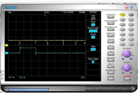
oscilogram.jpg

Here oscillogram clock - yellow, and frame blue.
I observe that the clock signal has a different width, the code for sending 1, 2,3 ... 8 bytes is the same.
Why is that?
 
I also made a program for data logging, until without writing to the memory card,
I wanted to make sure of the speed of the work and wanted to know how long it takes to read from the port and write to the buffer, and how long it takes to write to the card.
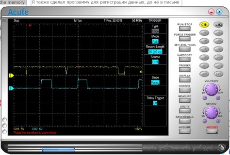
Here is the oscillogram - the yellow is the clock, the blue is the beginning and the end of the interruption.
you can see that the interrupt is triggered 1 microsecond after the clock.
This is normal? can I speed up the interrupt response time?
Code:
#define clocks 15    //15 pin Teensy3.2 - PORTC0 - signal clock for byte readiness
#define frame  16    //16 pin Teensy3.2 - PORTB0 - start of frame
#define stop_rec 17  //17 pin Teensy3.2 - PORTB1 - finish the recording and close the file
#define led 13
byte temp_byte =0;
byte bufer0[25600];//25600 samples * 0,00000390625 sec/1byte(256000 kGz) = 0.1sec = 100msec
byte bufer1[25600];
uint16_t pointer_buf_port2mem=0;
uint16_t pointer_buf_mem2card=0;
uint32_t frame_count =0;
uint32_t m10byteInFrame =0;
int val;
boolean bufer =0;
boolean enable_write=0;
boolean closeFile=0;
#define read8inline() ( (GPIOD_PDIR & B11111111)) // read 8bits from PORTD
void readPortD(void)
{
  digitalWriteFast(led, HIGH);// for test speed
  temp_byte =GPIOD_PDIR & B11111111;//read8inline();
//-------------------------  
  //select bufer
  if (bufer ==0)bufer0[pointer_buf_port2mem]=temp_byte; 
  else bufer1[pointer_buf_port2mem]=temp_byte; 
  pointer_buf_port2mem++;
  
  if(pointer_buf_port2mem >=25600)//if the buffer is full
  {
    pointer_buf_port2mem =0;
    bufer =!bufer;// select next bufer
    enable_write=1;
  }
  m10byteInFrame ++;
  if(m10byteInFrame >=9);//this is 10 byte in frame(0-9)
  {
    m10byteInFrame=0;
    frame_count++;
    // analis 9 byte, 4 bit = stop rec 
    if (bitRead(temp_byte, 4))closeFile=1;//This bit is also set by analyzing powermanager
  }
  digitalWriteFast(led, LOW);//for test speed
}

void stopRecords(void)
{
  // need close file in SD card
}
void setup() 
{
  //portD(0-7) 8 bits input
    pinMode(2, INPUT_PULLUP); 
    pinMode(14, INPUT_PULLUP); 
    pinMode(7, INPUT_PULLUP); 
    pinMode(8, INPUT_PULLUP); 
    pinMode(6, INPUT_PULLUP); 
    pinMode(20, INPUT_PULLUP); 
    pinMode(21, INPUT_PULLUP); 
    pinMode(5, INPUT_PULLUP);
  //control signals
    pinMode(led, OUTPUT);
    pinMode(clocks, INPUT_PULLUP);
    pinMode(frame, INPUT_PULLUP);
    pinMode(stop_rec, INPUT_PULLUP);  

    attachInterrupt (clocks, readPortD, RISING); //
}

void loop() 
{
  while(1)
  {
// if need records
  if (enable_write==1)
  {
    if (bufer ==0)
    {
      //write to SD card from bufer1
    }
    else
    {
      //write to SD card from bufer0
    }
    enable_write=0;
  }
    // test for low power
  val = analogRead(23);
  if(val<=945)closeFile=1;//if power down. This bit is also set by analyzing 9 byte
  if (closeFile==1) stopRecords();// if signal stop rec
  }
}

oscilogram2.jpg
 
It's time to share a working project.
2 tasks were solved:
1- Generator on Teensy3.2
2- Recorder on Teensy3.6
The generator issues 10 bytes (4 sines of 16 bits + 1 byte of saw +1 byte statuses) at a speed of ~ 256,000 bytes / sec. this data is synchronized by the Clock signal and the Frame.
The recorder receives the data and writes it to the memory card.
From the experiments I can conclude that the data rate can be increased by another 2.5 - 3 times, and maybe more.
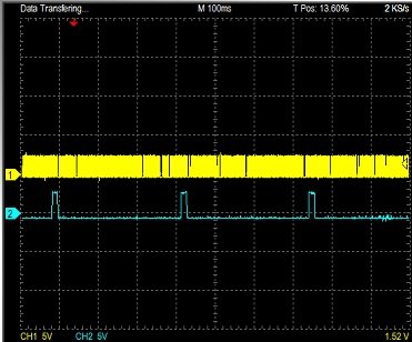
speed write.jpg
the blue line shows the recording time, sometimes it can exceed 100 milliseconds
generator code
Code:
const PROGMEM byte tab_sin[256] =
{ 
  0x7E, 0x7B, 0x78, 0x75, 0x72, 0x6F, 0x6C, 0x69, 0x66, 0x63, 0x60, 0x5D, 0x5A, 0x57, 0x54, 0x51, 
  0x4E, 0x4B, 0x48, 0x45, 0x43, 0x40, 0x3D, 0x3B, 0x38, 0x35, 0x33, 0x30, 0x2E, 0x2C, 0x29, 0x27, 
  0x25, 0x23, 0x20, 0x1E, 0x1C, 0x1A, 0x18, 0x17, 0x15, 0x13, 0x12, 0x10, 0x0E, 0x0D, 0x0C, 0x0A,
  0x09, 0x08, 0x07, 0x06, 0x05, 0x04, 0x03, 0x03, 0x02, 0x01, 0x01, 0x00, 0x00, 0x00, 0x00, 0x00,
  0x00, 0x00, 0x00, 0x00, 0x00, 0x00, 0x01, 0x01, 0x02, 0x03, 0x03, 0x04, 0x05, 0x06, 0x07, 0x08,
  0x09, 0x0A, 0x0C, 0x0D, 0x0E, 0x10, 0x12, 0x13, 0x15, 0x17, 0x18, 0x1A, 0x1C, 0x1E, 0x20, 0x23,
  0x25, 0x27, 0x29, 0x2C, 0x2E, 0x30, 0x33, 0x35, 0x38, 0x3B, 0x3D, 0x40, 0x43, 0x45, 0x48, 0x4B, 
  0x4E, 0x51, 0x54, 0x57, 0x5A, 0x5D, 0x60, 0x63, 0x66, 0x69, 0x6C, 0x6F, 0x72, 0x75, 0x78, 0x7B, 
  0x7E, 0x82, 0x85, 0x88, 0x8B, 0x8E, 0x91, 0x94, 0x97, 0x9A, 0x9D, 0xA0, 0xA3, 0xA6, 0xA9, 0xAC,
  0xAF, 0xB2, 0xB5, 0xB8, 0xBA, 0xBD, 0xC0, 0xC2, 0xC5, 0xC8, 0xCA, 0xCD, 0xCF, 0xD1, 0xD4, 0xD6,
  0xD8, 0xDA, 0xDD, 0xDF, 0xE1, 0xE3, 0xE5, 0xE6, 0xE8, 0xEA, 0xEB, 0xED, 0xEF, 0xF0, 0xF1, 0xF3,
  0xF4, 0xF5, 0xF6, 0xF7, 0xF8, 0xF9, 0xFA, 0xFA, 0xFB, 0xFC, 0xFC, 0xFD, 0xFD, 0xFD, 0xFD, 0xFD,
  0xFE, 0xFD, 0xFD, 0xFD, 0xFD, 0xFD, 0xFC, 0xFC, 0xFB, 0xFA, 0xFA, 0xF9, 0xF8, 0xF7, 0xF6, 0xF5,
  0xF4, 0xF3, 0xF1, 0xF0, 0xEF, 0xED, 0xEB, 0xEA, 0xE8, 0xE6, 0xE5, 0xE3, 0xE1, 0xDF, 0xDD, 0xDA,
  0xD8, 0xD6, 0xD4, 0xD1, 0xCF, 0xCD, 0xCA, 0xC8, 0xC5, 0xC2, 0xC0, 0xBD, 0xBA, 0xB8, 0xB5, 0xB2,
  0xAF, 0xAC, 0xA9, 0xA6, 0xA3, 0xA0, 0x9D, 0x9A, 0x97, 0x94, 0x91, 0x8E, 0x8B, 0x88, 0x85, 0x82 
};
#define clocks 15    //15 pin Teensy3.2 - PORTC0 - signal clock for byte readiness
#define frame  16    //16 pin Teensy3.2 - PORTB0 - start of frame
#define led 13
uint32_t max_byte=0;//The device should not work more than 5 minutes. During this time 76800000 bytes will be stored  
uint8_t pointer0sin;//does nothing, for the same synchronization length
uint8_t pointer1sin=0;//0 degres;
uint8_t pointer2sin=1;//32;//45 degres;
uint8_t pointer3sin=2;//64;//90
uint8_t pointer4sin=3;//128;//180
uint8_t my9_byte=0;// 9 byte - 8 bit saw
uint8_t my10_byte=0;// 10 byte - status bits

#define myDelay 2

void Sinhro(void)
{               
  delayMicroseconds(1);
  digitalWriteFast(clocks, LOW);
  delayMicroseconds(2);
  digitalWriteFast(clocks, HIGH);
  max_byte++;
}
void setup() 
{
  pinMode(led, OUTPUT);
  pinMode(clocks, OUTPUT);
  digitalWriteFast(clocks, HIGH);// synchronization     
  pinMode(frame, OUTPUT);
  
  pinMode(2, OUTPUT);//D0 
  pinMode(14, OUTPUT); //D1
  pinMode(7, OUTPUT);//D2
  pinMode(8, OUTPUT);//D3
  pinMode(6, OUTPUT);//D4
  pinMode(20, OUTPUT);//D5
  pinMode(21, OUTPUT);//D6
  pinMode(5, OUTPUT); //D7
  
}
void loop() 
{
  while(1) 
  { 
//Sine wave 1   
//high byte write       
    GPIOD_PDOR=tab_sin[pointer1sin];// high byte of value 
    digitalWriteFast(frame, HIGH);// beginning of frame   
    Sinhro();
//low byte write     
    GPIOD_PDOR=tab_sin[pointer1sin];// high byte of value 
    digitalWriteFast(frame, LOW);// within a frame           
    Sinhro();
    pointer1sin++;
    
//Sine wave 2   
//high byte write    
    GPIOD_PDOR=tab_sin[pointer2sin];// high byte of value
    Sinhro();
//low byte write    
    GPIOD_PDOR=tab_sin[pointer2sin];// low byte of value       
    Sinhro(); 
    pointer2sin++;

//Sine wave 3   
//high byte write     
    GPIOD_PDOR=tab_sin[pointer3sin];//high byte of value    
    Sinhro();
//low byte write    
    GPIOD_PDOR=tab_sin[pointer3sin];// low byte of value
    Sinhro();
    pointer3sin++;

//Sine wave 4   
//high byte write     
    GPIOD_PDOR=tab_sin[pointer4sin];//high byte of value    
    Sinhro();
//low byte write    
    GPIOD_PDOR=tab_sin[pointer4sin];// low byte of value   
    Sinhro();
    pointer4sin++;

//9 and 10 byte   
//9 byte write 
        
    GPIOD_PDOR=my9_byte;// 9 byte
    Sinhro();
    my9_byte++;   
    
//10 byte write 
   
    if(max_byte < 76800000)//7680000*10(byte in frame) 76800000 byts * 4uSec
    {
     digitalWriteFast(led, LOW);//
     digitalWriteFast(stop_rec, LOW);// 
     my10_byte=0x00;
    }
    else 
    {             
      bitWrite(my10_byte, 4, 1);//bitSet(my10_byte, 4);//my10_byte =1<<4;
      digitalWriteFast(led, HIGH);//
      digitalWriteFast(stop_rec, HIGH);//
    }
  
    GPIOD_PDOR=my10_byte;// 10 byte
    Sinhro();     
  }  
}

code for loger
Code:
//This sketch is based on the examples of www.pjrc.com

#define read8inline() ( (GPIOD_PDIR & B11111111)) //macro for read 8 low bits from portD

#include <SPI.h>
#include "SdFat.h"
// Set USE_SDIO to zero for SPI card access. 
#define USE_SDIO 1
// SD chip select pin.  Be sure to disable any other SPI devices such as Enet.
const uint8_t chipSelect = SS;

// Error messages stored in flash.
#define error(msg) sd.errorHalt(F(msg))

// file system
#if USE_SDIO
// Traditional DMA version.
// SdFatSdio sd;
// Faster version.
SdFatSdioEX sd;
#else  // USE_SDIO
SdFat sd;
#endif  // USE_SDIO
// test file
SdFile file;
// Log file base name.  Must be six characters or less.
#define FILE_BASE_NAME "Data"
const uint8_t BASE_NAME_SIZE = sizeof(FILE_BASE_NAME) - 1;
char fileName[13] = FILE_BASE_NAME "00.raw";
//==============================================================================
uint32_t frame_count =0;
int switchBuf=0;// select activ bufer 0 or 1
int enable_write=0;//need write
int closeFile=0;// need stop write to card and close file
int pointer_buf_port2mem=0;
int BufSize=102400;//256000sample per second = 1 sample per 0,00000390625 S *102400=400mS
//While in one buffer is used to collect data,
//the other is used to copy data to a memory card,
//after - change places
byte  bufer0[102400];//
byte  bufer1[102400];//
byte  temp_byte =0;//

#define clocks 15    //15 pin Teensy3.6 - PORTC0 - signal clock for byte readiness
#define frame  16    //16 pin Teensy3.6 - PORTB0 - start of frame
#define led 13

//==============================================================================
 void readPortD(void)
{
  temp_byte =read8inline();
  if(digitalReadFast(frame))frame_count =0;//this is the beginning of the frame
  else frame_count++;
 
  //select bufer
  if (switchBuf ==0) bufer0[pointer_buf_port2mem]=temp_byte; 
  else bufer1[pointer_buf_port2mem]=temp_byte;  
  pointer_buf_port2mem++;
  
  if(pointer_buf_port2mem >=BufSize)//if the buffer is full
    {
      pointer_buf_port2mem =0;//pointer to the beginning of the buffer
      if(switchBuf ==0)switchBuf=1;//change active buffer
      else switchBuf=0;     
      enable_write=1;
    }

  if(frame_count >=9)//this is 10 byte in frame(0-9)
    { 
      // analis 9 byte, 4 bit = stop rec 
      if (bitRead(temp_byte, 4))
        {
          detachInterrupt(clocks);//The interrupt is no needed  
          closeFile=1;//This bit is also set by analyzing powermanager
        }  
    }
}
//------------------------------------------------------------------------------

void setup() 
{
   //portD(0-7) 8 bits input
    pinMode(2, INPUT_PULLUP); 
    pinMode(14, INPUT_PULLUP); 
    pinMode(7, INPUT_PULLUP); 
    pinMode(8, INPUT_PULLUP); 
    pinMode(6, INPUT_PULLUP); 
    pinMode(20, INPUT_PULLUP); 
    pinMode(21, INPUT_PULLUP); 
    pinMode(5, INPUT_PULLUP);
  //control signals
    pinMode(led, OUTPUT);
    pinMode(clocks, INPUT_PULLUP);
    pinMode(frame, INPUT_PULLUP);
 
  // Initialize at the highest speed supported by the board that is
  // not over 50 MHz. Try a lower speed if SPI errors occur.
  if (!sd.begin()) 
  {
   // sd.initErrorHalt(); 
    finish_p();  
  }
  
//test free memory; it will probably be used in future versions
uint32_t volFree = sd.vol()->freeClusterCount();

//-----------
//Test for the existence of a file.
//here the presence of a file with a base name is checked,
//if it is missing, then it is created, if it is, then a new one with an increment of the number  
//here is a mystery; I did not get to the bottom and just copied this part 
//the author of these lines is undoubtedly a great shaman   
  while (sd.exists(fileName)) {
    if (fileName[BASE_NAME_SIZE + 1] != '9') {
      fileName[BASE_NAME_SIZE + 1]++;
    } else if (fileName[BASE_NAME_SIZE] != '9') {
      fileName[BASE_NAME_SIZE + 1] = '0';
      fileName[BASE_NAME_SIZE]++;
    } else {
      //error("Can't create file name"); 
      finish_p();      
    }
  }
  if (!file.open(fileName, O_CREAT | O_WRITE | O_EXCL)) 
  {
    //error("file.open");
    finish_p();
  }

//-------------
//waiting for the synchronization from the beginning of the frame
  while (!digitalReadFast(frame)){};
  //-----------------
  //this part is here because the interrupt does not have time to work for the first time,
  //and skips the first byte    
  bufer0[pointer_buf_port2mem]=read8inline();
  pointer_buf_port2mem++;
  //-----------------
  attachInterrupt (clocks, readPortD, FALLING); //
}
//------------------------------------------------------------------------------
void loop() 
{     
  if (enable_write==1)// if need records
    {
      digitalWriteFast(led, HIGH);// for test speed
      switch(switchBuf)
        {
          case 0: //while we collect data into the buffer 0 - write to the card from the buffer1  
            file.write(bufer1,BufSize);
            break;
          case 1: //while we collect data into the buffer 1 - write to the card from the buffer0  
            file.write(bufer0,BufSize);
            break;
        }
        // Force data to SD and update the directory entry to avoid data loss.
        if (!file.sync() || file.getWriteError()) {
        error("write error");
        }     
      enable_write=0;
      digitalWriteFast(led, LOW);//for test speed
    }
  // test for low power
  if(analogRead(32)<=945)closeFile=1;//if power down. This bit is also set by analyzing 9 byte(0-9)
  if (closeFile) // if signal stop rec
    {
      detachInterrupt(clocks);
      switch(switchBuf)
        {
          case 0: 
            file.write(bufer0,pointer_buf_port2mem);
            break;
          case 1:
            file.write(bufer1,pointer_buf_port2mem);
            break;
        }
      file.close();
      finish_p();
    } 
}
//finish programm 
void finish_p(void)
{
 //portD(0-7) 8 bits input
    pinMode(2, INPUT); 
    pinMode(14, INPUT); 
    pinMode(7, INPUT); 
    pinMode(8, INPUT); 
    pinMode(6, INPUT); 
    pinMode(20, INPUT); 
    pinMode(21, INPUT); 
    pinMode(5, INPUT);
  //control signals
    pinMode(led, INPUT);
    pinMode(clocks, INPUT);
    pinMode(frame, INPUT);
 while(1)
 {}  
}


Paul! You're doing a great job. Thank you!
Also thanks to Bill Greiman!
Thank you!!!!
 
Last edited:
I can't compile the project (text above).
Everything was great before. I am currently using Arduino 1.8.19 +
Teensyduino 1.57.
What's wrong? How to change a project?
Help me please? I'm using Teensy3.6, I need maximum card write speed

TeensySdioLogger:13: error: 'sd' was not declared in this scope
#define error(msg) sd.errorHalt(F(msg))
^
C:\Users\LUKASH~1\AppData\Local\Temp\arduino_modified_sketch_239960\TeensySdioLogger.ino:158:9: note: in expansion of macro 'error'
error("write error");
^
'SdFatSdioEX' does not name a type
 
Last edited:
Back
Top