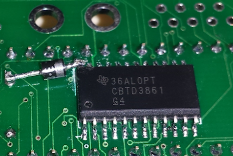
Sn74cbtd3861

Status
Not open for further replies.

Frank B

Senior Member
Datasheet : http://www.ti.com/lit/ds/scds084g/scds084g.pdf
(See page 5 with diagrams)

This is a bidirectional levelshifter. According to the datasheet, the output-voltage should be about 3V. VCC is 5.19 Volt.
If I add a 1K pullup (to VCC) to a "A" pin, "B" is about 3.55 Volt, which is a little too much.. and more than stated in the datasheet. How can this be ? Am I overlooking something ?

Is 3.55 Volt OK for the Teensy 3.6 ? (Pin-config will be OUPUT_OPENDRAIN)
 
Last edited:
Datasheet : http://www.ti.com/lit/ds/scds084g/scds084g.pdf
(See page 5 with diagrams)

This is a bidirectional levelshifter. According to the datasheet, the output-voltage should be about 3V. VCC is 5.19 Volt.
If I add a 1K pullup (to VCC) to a "A" pin, "B" is about 3.55 Volt, which is a little too much.. and more than stated in the datasheet. How can this be ? Am I overlooking something ?

Is 3.55 Volt OK for the Teensy 3.6 ? (Pin-config will be OUPUT_OPENDRAIN)

My fix... added a diode between 5v <--> chip-vcc

No perfect, but sufficient at the moment: 3.15 V on the outputs.
2017-10-11 21.55.07.png
 
Last edited:
Do I really need a 5V low drop voltage regulator ? Or, would you say I can use the diode for the final board ?
 
I look at an image from google where a person scoped the inputs vs outputs. What you ended up was what does not have. 5 v in = 3 v out Approx. The docs says a diode is on Vcc already as well.
Bad IC? Maybe a stray ac signal causing a rectified signal to become an adder. Maybe you are too close to a Radio/TV station and the power is to high. Maybe some has a big telsa coil outside your door.
But this is not logical
 
The additional diode is to reduce the voltage a little bit (about 0.7 volt). I don't really like that, but it was the easiest/fastest way to fix the board..
Where did you find that on google ?


Edit: I think now, the datasheet is wrong - or better: not exact..
 
Last edited:
Oh.. I read in a datasheet for a similar chip that the diode is good :) That's luck... no regulator needed.

Thanks for listening.
 
:) - glad to listen Frank. Nice you found a related application note of some sort to confirm the easy fix you did was a good approach.
 
Did not try that, but I tried input_pulldown on the teensy (around ~30K). Does not change anything. An additional pulldown would increase the amount of resistors by 9, too... not a option I'd like.
What helps, is to use weaker pullups (is that mentioned in the datasheet ?) But, again not an option, because the original c64 design uses 1K pullups, and I want to make that compatible.
Anway, the diode is a good solution, and I've decided to use it.
 
Status
Not open for further replies.
Back
Top