Trouble with analog ports on Teensy3.6

Status
Not open for further replies.

Anton_H

Active member
Solved - the problem was failed solder on GND pin

Hi everyone,

I'm trying to get a photoresistor working on my Teensy3.6. This is the code:
Code:
void setup() {
  // put your setup code here, to run once:
  pinMode(34, INPUT_PULLUP);
  pinMode(33, OUTPUT);
  digitalWrite(33, HIGH);
  Serial.begin(9600);
}

void loop() {
  // put your main code here, to run repeatedly:
  Serial.println(analogRead(34));
  delay(200);
}

When I place my finger on the photoresistor, so there's no light, the value should be 0.
When I place the torch of my phone in front of the photoresistor, the value should be (and is) 1023.

But when I place my finger on the photoresistor, I got +/- 1015 as value. This is far from what it should be and the values are for too close to be able to do something with it.

When I disconnect the photoresistor, so there's nothing in the analog port, the value that I get is around 970. Is that normal?

Can someone help me?


Thanks in advance!
 
Last edited:
try getting rid of pinMode(34, INPUT_PULLUP);

edit: doesn't matter, analogRead() overrides the pinMode(). FWIW, your sketch works for me with my photo-resistorr on T3.6 (3v3-PR-x-2k2-GND )
 
Last edited:
The code does not show us the full picture without knowing how this photoresistor is connected. I assume this is a CdS or CdSn (cadmium sulfide / cadmium selenide) device.

Normally you would make a resistive divider with one normal fixed resistor and one photoresistor in series, going from a supply voltage like 3.3V to ground. With that connection, the voltage at the connection between the two devices (where you'd also have your ADC input pin connected) will change with the ambient light level as the photoresistor value changes. Whether the voltage goes up or down with light level depends on whether the photo resistor is on the top or the bottom of the resistive divider. The resistance of a photoresistor goes down as the light level increases. Note also the response time can be slow, it can be many seconds if the light level very low.

The circuit I'm thinking of is like this (except 3.3V instead of 5V as the Teensy's analog inputs are not 5V tolerant)
http://cdn.instructables.com/FHK/OBT5/HO2346L3/FHKOBT5HO2346L3.MEDIUM.jpg
 
try getting rid of pinMode(34, INPUT_PULLUP);
How should I do that?

The code does not show us the full picture without knowing how this photoresistor is connected.
One side of the photoresistor too pin 33 (input of the photoresistor), and the other pin too pin 34 (output of the photoresistor).

I assume this is a CdS or CdSn (cadmium sulfide / cadmium selenide) device.
No idea what it is, I bought it a long time ago on Amazon for very cheap.

Normally you would make a resistive divider with one normal fixed resistor and one photoresistor in series, going from a supply voltage like 3.3V to ground. With that connection, the voltage at the connection between the two devices (where you'd also have your ADC input pin connected) will change with the ambient light level as the photoresistor value changes. Whether the voltage goes up or down with light level depends on whether the photo resistor is on the top or the bottom of the resistive divider. The resistance of a photoresistor goes down as the light level increases. Note also the response time can be slow, it can be many seconds if the light level very low.
So you think the problem is in my wiring?

Thank you both for your answers.
 
So you are making pin 33 as a supply for one leg of the photo device and then placing the other end to pin 34 as input. So a resistor between 33 and 34 and 33 supplying around supply. You are basically pulling the input HI to 33 and eve though you are trying to detect a change, you will probably not.
You need to make it see a voltage change like a control.. place a resistor from 3.3 v to 34. Like 10K or so but this will likely depend al lot of the value of the photoResistor. Then place one of the the PR to 34 and the other to ground.
Take a ohm meter and measure the resistance between the leads of the PR and change the light to it. Find the values so you can determin the vale of the resistor between 3.3v and 34.
 
Okay, I got it working, thanks for your help, but I'm not finished (sorry).
I wanted to got that photoresistor working to test the analog ports of my Teensy board. That seems okay.

I wanted to test them because my Pololu QTR-8A line-sensor is actually not working.

This is my wiring:

Pololu sensor | Teensy
GND | GND
VCC | 3.3V
1 | port 14 (= analog 0)
2 | port 15 (= analog 1)
3 | port 16 (= analog 2)
4 | port 17 (= analog 3)
5 | port 18 (= analog 4)
6 | port 19 (= analog 5)
7 | port 20 (= analog 6)
8 | port 21 (= analog 7)

And the little test code is:
Code:
void setup() {
  // put your setup code here, to run once:
  pinMode(14, INPUT);
  Serial.begin(9600);
}

void loop() {
  // put your main code here, to run repeatedly:
  Serial.println(analogRead(14));
  delay(200);
}

And I get always the same values, even with my finger on it or with the torch of my phone in front of it ...
 
That is an interesting module. Did you jumper the pins for 3.3 volt operation? The spec write up says Optimal sensing distance: 0.125" (3 mm). Try moving a piece of white paper very close to the unit.
 
I don’t need to jump the 3.3V shortcut since I am not using the emitters, and I already tried it on another module (have plenty of them) and I got the same results. And I already tried the thing with the paper. Will post a photo of the wiring this evening when I am home.
 
I tried to upload a photo of my wiring, but I alway get an error message, sorry for it.
But I'm sure my wiring is correct, I checked it 1000000 times. The wiring is as follow:

Pololu sensor | Teensy
GND | GND
VCC | 3.3V
1 | port 14 (= analog 0)
2 | port 15 (= analog 1)
3 | port 16 (= analog 2)
4 | port 17 (= analog 3)
5 | port 18 (= analog 4)
6 | port 19 (= analog 5)
7 | port 20 (= analog 6)
8 | port 21 (= analog 7)
 
Photos IIRC have a 1MB limit -

Carefully do a quick test with jumper of GND and then 3.3V to your test pin(s) - perhaps move test to analog pin not connected to a device like pin 22/A8?
 
Got the exactly the same on pin 33 (A14). The problem isn't with the analog ports (therefore that I needed to got the photoresistors working).
Photos IIRC have a 1MB limit
What does that mean and what is IIRC?

Carefully do a quick test with jumper of GND and then 3.3V to your test pin(s)
On 3.3V I got 1023 and with GND I got 1
 
Got the exactly the same on pin 33 (A14). The problem isn't with the analog ports (therefore that I needed to got the photoresistors working).

On 3.3V I got 1023 and with GND I got 1

Indeed with those values for 3.3V and GND you have working 10 bit analog read from that/those tested pins.

...
What does that mean and what is IIRC?

IIRC >> If I Recall Correctly

A JPG or PNG upload is limited to 1MB in size, IIRC - last I saw 1MB was the limit on uploaded images.
 
Again helps to see picture of wiring, plus current code. For example you say that:
Code:
Pololu sensor | Teensy
GND | GND
VCC | 3.3V
1 | port 14 (= analog 0)
2 | port 15 (= analog 1)
3 | port 16 (= analog 2)
4 | port 17 (= analog 3)
5 | port 18 (= analog 4)
6 | port 19 (= analog 5)
7 | port 20 (= analog 6)
8 | port 21 (= analog 7)

I could not tell with my 10 second look at the Pololu page: https://www.pololu.com/product/960
If the product works with 3.3v connected to VIN or if you need to use the 3.3v bypass connections?

analogRead is sort of funky with the pin numbers passed to it: 0-13 are A0-A13
And: 14-23 are for A0-A9
After that it is pin numbers...

So as others mentioned, pictures help... Helps see things like are you using breadboard... Are the pins soldered in...
 
img_1921_copy_2.jpg
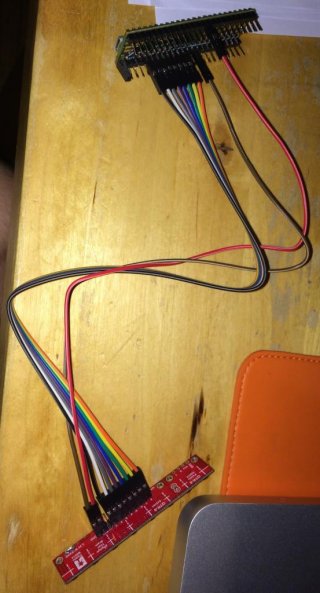
Hope the photo is clear, let me know if not (and what you would like to see).
 
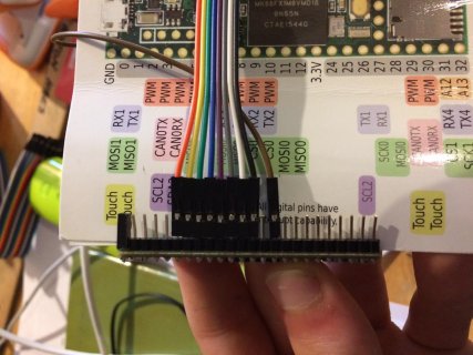
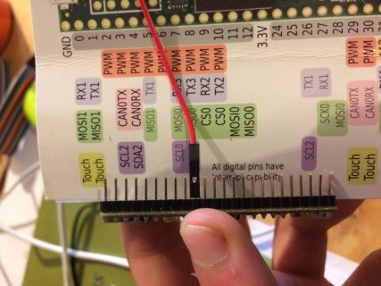
From your picture it is unclear on how you are powering the sensor. The Red wire looks like it goes to the 5th pin from the right on top row... Like pin 38... Not going to 3.3v pin?
 
It is connected to 10th pin from the right top. When I unplug that one (no power) my values are around 450 (in case of values around 950). So it's definitely the 3.3V.
 
The Brown/Black wire I believe is on 10th pin which I believe is GND... It is the RED wire that looks like it is on the 5th pin... Again Could be wrong... The 3.3v would be on the bottom 10th pin from right, or on top 3rd pin from top left
 
That picture puzzled me too - the red is up 10 pins on the opposite side of the GND. And the lines are red and brown single - the shadows make it look like a paired black wire.
 
That picture puzzled me too - the red is up 10 pins on the opposite side of the GND. And the lines are red and brown single - the shadows make it look like a paired black wire.

<posted earlier - but on wrong thread >
 
Thanks pictures look more clear. I think in your first picture you show the 3.3v bypass being soldered?

Does it show the same for all 8 analog inputs?

What happens if your code looks like:
Code:
void setup() {
    while (!Serial) ; // wait for Serial port
    Serial.begin(115200);  // not strictly needed
}

void loop() {
    for (int i = A0; i < A8; i++) {
        Serial.print(analogRead(i));
        Serial.print(" ");
    }
    Serial.println();
    delay(250);
}

do any of the values change as you move your hand or light near the sensors? The reason I ask some of this is I have at times had some of these type of jumper not make proper contact. So would be good to see if any of them are working properly or not...

Also if you soldered the pins versus purchased with pins... Check for any cold solder connections. I sometimes on general principal quickly touch each pin with hot soldering iron to maybe correct...
 
Okay, I found the problem: the soldering of the GND-pin was broken ... Thanks to everyone for your help!
 
Do I have to close this thread, and if I have to, were is the button to do it (because I do not see it).
 
Status
Not open for further replies.
Back
Top