OctoWS2811 - Pinout

Status
Not open for further replies.

netmindz

Member
I love the OctoWS2811, it works perfectly for driving my LEDs, but one issue I cam across after ordering is that not all the pins are presented on the board, so if you are say trying to add an audio input or say ambient light sensor, you are rather restricted

Is this because the other pins are not possible to use when driving the OctoWS2811 or that board space was limited so you only presented the ones you needed for your projects?
 
Hi Paul

That's for the 3.5/3.6 not the 3.2 that fits with the Octo

Perhaps to clarify my question - are pins 0,1,23,22,19,18,17 the only ones that I should attempt to use or could i use other pins if i put some form of shield between the teensy and the octo in order to breakout other stuff?
 
Hi Paul

That's for the 3.5/3.6 not the 3.2 that fits with the Octo

Perhaps to clarify my question - are pins 0,1,23,22,19,18,17 the only ones that I should attempt to use or could i use other pins if i put some form of shield between the teensy and the octo in order to breakout other stuff?
Obviously Paul is the one with the knowledge, but given the Octowswi11 shield has no connection to any of the pins brought out to solder pads underneath the Teensy, I would imagine you can use them for normal usage. If you use them for DMA, high speed SPI, etc. you may need to go datasheet deep diving.

Perhaps the simplest breakout board is the one Frank B designed that uses castlelated (spelling) holes to match the solder pads, and brings out the pins in a row of 2x7 at the back:

Here is a board designed by somebody called CPT:

Here is a board designed by Talldog, that is offered at Tindie:
 
or could i use other pins if i put some form of shield between the teensy and the octo in order to breakout other stuff?

Yes, you can use all other pins which are not used by OctoWS2811.

On Teensy 3.2 & 3.5, one extra pin is reserved and must not be used. On all boards, 1 or 2 of the pins can not be used as PWM because OctoWS2811 uses the FTM timer which control those pins, but you can use them for ordinary digitalRead & digitalWrite. Likewise, other libraries which use that timer would conflict with OctoWS2811, regardless of how they use the pins.

Details about which pins are reserved can be found on the OctoWS2811 documentation page under "Hardware Requirements".

https://www.pjrc.com/teensy/td_libs_OctoWS2811.html

All the other pins not mentioned as used by OctoWS2811 are available. How you physically connect the wires is up to you. Obviously the 7 pins which the Octo board brings to the edge are easiest.
 
I just received and wanted to be sure that I connected my Teeny 3.2 + SD Card + OctoWS2811 correctly. I have read and noted the information found in the OctoWS2811 folder on github:

https://github.com/PaulStoffregen/OctoWS2811/blob/master/examples/VideoSDcard/VideoSDcard.ino

Within the header of this source file I found this information written with the Teensy 3.1 as the Primary Teensy to use, does this code below mirror directly over to the Teensy 3.2?

Code:
Update: The programs to prepare the SD card video file have moved to "extras"
https://github.com/PaulStoffregen/OctoWS2811/tree/master/extras
  The recommended hardware for SD card playing is:
    Teensy 3.1:     http://www.pjrc.com/store/teensy31.html
    Octo28 Apaptor: http://www.pjrc.com/store/octo28_adaptor.html
    SD Adaptor:     http://www.pjrc.com/store/wiz820_sd_adaptor.html
    Long Pins:      http://www.digikey.com/product-search/en?keywords=S1082E-36-ND
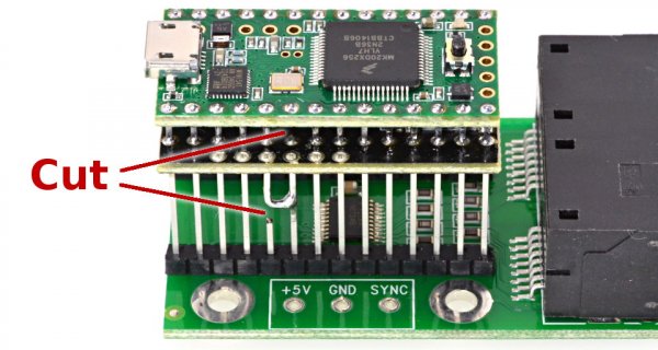
  See the included "hardware.jpg" image for suggested pin connections,
  with 2 cuts and 1 solder bridge needed for the SD card pin 3 chip select.
 
  Required Connections
  --------------------
    pin 2:  LED Strip #1    OctoWS2811 drives 8 LED Strips.
    pin 14: LED strip #2    All 8 are the same length.
    pin 7:  LED strip #3
    pin 8:  LED strip #4    A 100 to 220 ohm resistor should used
    pin 6:  LED strip #5    between each Teensy pin and the
    pin 20: LED strip #6    wire to the LED strip, to minimize
    pin 21: LED strip #7    high frequency ringining & noise.
    pin 5:  LED strip #8
    pin 15 & 16 - Connect together, but do not use
    pin 4:  Do not use
    pin 3:  SD Card, CS
    pin 11: SD Card, MOSI
    pin 12: SD Card, MISO
    pin 13: SD Card, SCLK
*/

Here is a picture which looks like a Teensy 3.2 with its Pin 4 CUT, and the SDcard Pin 3 and 4 connected and tied into the Octos Pin 4. Here is its image and link to this:https://github.com/PaulStoffregen/OctoWS2811/blob/master/extras/VideoSDcard/hardware.jpg

hardware.jpg

If all the above is correct, do you by chance have an image available for the other side to see how the Teensy 3.2 Pins 15 and 16 look or do I just connect them and not run them to the OctoWS, in this image I see from the top that pin 15 and 16 are Soldered, so do they each run down to the OctoWS2811 and connect within the OctoWS board together? Or do I just make a loop as we see from the SDcard pin 3 to 4 (but connection pins 15 and 16 on the Teensy)?

I'm currently not looking to use the free pins as mentioned above, just want to connect all correctly so there are not shorts, and when a SD card is placed into the SDcard it will play via the Teensy 3.2 and Octo to the led sign 32x60.

Note that the OctoWS2811 + Teensy 3.2 + SDcard reader will all be powered via the Octos 5v and ground. No other usb will be attached to the Teensy.

Thanks for your help and time.
 
Status
Not open for further replies.
Back
Top