Ignition controller for ODD Fire V6 coil near plug

Status
Not open for further replies.
We have an Odd Fire V6 engine, it’s firing order is cylinder 1,5,2,4,3,6 at static timing of 0, 45, 120, 165, 240, 285 degrees.
The current ignition system has failed and is no longer serviceable. We have not been able to find an alternative system that can work with the Odd firing. I have looked at megasquirt and others.
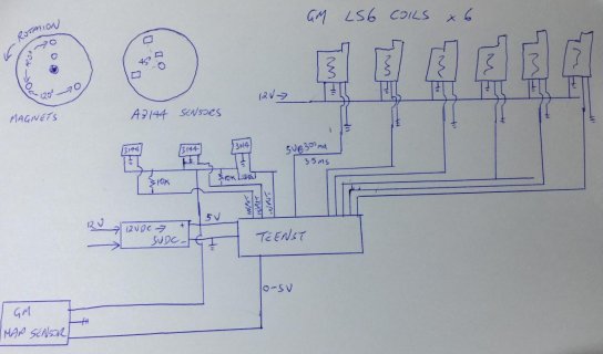
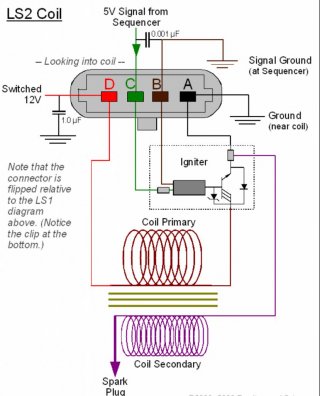
Going to our parts bin we found these great GM coils that fit close to each spark plug. Each coil requires 5V, 300milamp for 3.5ms basically.
Using an old distributor we can set 3 magnets 120 degrees apart plus another magnet on a different radius to trigger a complete rotation.
Using 2 Hall effect sensors 45 degrees apart we can create even firings, one sensor for cylinders one two and three, the other sensor for cylinders four five and six.
The third Hall effect sensor is simply to signal completion of rotation and start the firing order again.

So with great mechanical and machinery skills, no electronic and little coding I am trying to get this to work.

Currently we just need to get this engine to fire, no need to worry about engine timing advance at this point.

Any guidence on circuit design and code would be very helpful.

Very simple process would be something like this :
Loop
// TDC sensor starts ignition sequence

Interrupt on TDC sensor sets Leftcoil =1 and RightCoil =4

// Sensor Left ignites Coils 1, 2 and 3
Interrupt Left Sensor is high then Coil 1 is high for 3.5ms
LeftCoil = leftCoil + 1

// Sensor Right ignites Coils 4,5,6
Interrupt Right Sensor is high then Coil 3 is high for
3.5ms
RightCoil = RightCoil + 1


BB0D4231-B9BE-411E-B0C8-4BBD12C4D3FE.jpg
 
Further guidence as to which Teensy and or if Teensy will work ?
Some numbers:-
Distributor rotates at a maximum 4,000 rpm
6 coils firing individually 4,000 per minute or 24,000 total firing
 
A teensy can work. the 5V teensy(T2) two would make the interface easier but be slower and offer little over a classic arduino (see below). A teensy 3.2 would offer more processing power to hit the 400/s firing pulses but add extra circitry to get the voltage/current mix to trigger the coils. That said 400/s is very low in microprocessor terms so pretty much an CPU can do it, even if you get clever having adjustable timing offset on RPM. What is complex here is the environment you need this to work on. Many many car based projects have suffered strange glitches and problems from ignition noise and this project is connected directly to the ignition system so much harder to shield and also has failure mode 'engine fires in reverse at 100' rather than 'stereo glitches'. Would suggest some googling around for ignition controller project that have faced down the isolation problems and seeing what they did/how they overcome the problems and possibly basing your design on whatever hardware is proven to work rather than picking a cpu and working out how to Armour it.

A teensy can certainly do this code/performance wise, the question is how much experience you have and test equipment you can get hold of to grapple with the problem of measuring engine position and driving the spark without being swapped by interference and destroying the CPU and/or engine in a cascade of random commands.
 
GremlinWrangler thank for your comments, I understand your comments interference and the machinical damage random sparks can cause. I have seen first hand interference destroy race car engines.

In this application I am intending on using these GM LS2 coils, in their original setup the coils are mounted about a metre from their original ECU and the signal wires run next to the power wires without any shielding. I hope by using some shielding and capacitors to clean the signal I can get them to work.

I can mount a Teensy within the old distributor under the Hall effect sensors, as I am no longer distributing spark all the distributor is doing is low voltage.

Unlike other more complex systems that use multiple teeth with a missing tooth to calculate engine positioning I am just using 3 Hall effect sensors.

Smarter minds than mine may suggest capacitors and resistors for signal cleaning both on the signals from the Hall effect sensors and signals sent to the coils.

CD00E3DB-D00D-4A42-9BB9-283A49BE0D0D.jpg
 
I can mount a Teensy within the old distributor under the Hall effect sensors,

View attachment 11961

You should not put the teensy in the distributor in my opinion - electrical noise will be the least of your worries! The harmonics from crank and camshaft will likely remove the components from the board, plus you will see temperatures well over 100deg C.

Very interested in your project.
I spent many weeks with VR-sensor + missing tooth wheel equipped angle-grinder in hand, trouble-shooting tooth-tables on a 13000rpm Suzuki with GT3076R Turbo. Problem was the processor (professional stand-alone ECU) was not fast enough to start the engine safely. It happily made 350bhp from the little 998cc, but could not cope with the rapid rpm change created by the first combustion event, and the engine was destroyed by the miss-timed spark during starter-cranking.

There are some interesting Arduino Automotive ECU projects scattered across the internet at present.

The problem I see is that with 3 sensors attached to the dizzy you will get 1 pulse every 240 deg crank rotation (dizzy rotates at half engine speed) You need to charge the coils for a variable amount of time prior to Top Dead Centre, but your known crank position is only +/-120 degrees accuracy. On a 6 cylinder engine the rpm oscillates 3 times per crank revolution, but you have no measurment or even an estimation of instantaneous engine speed. I guess you might get this to work with a high-inertia (low compression, heavy flywheel) engine.

Another consideration is magnets do not like too much heat, and are difficult to keep where you want them (too brittle for interference fit). Hall-effect does not need a rotating magnet, camshaft sensors are often hall effect and use a mild-steel pin (the magnet is in the sensor).

You will not be able to connect the teensy directly to your coils as per your diagram, you will need a driver IC for each individual coil.

Good luck and please post your progress.

Darcy.
 
Last edited:
Darcy,

I have seen lots of other ignition projects using all types of processors. Whilst I am trying to learn as much as I can from those projects none will work with the odd Fire caused by the different cyclinder angles I have.
 
Mathematically, a 24 tooth hall sensor would solve the problem, dividing the 360° into "slices" of 15°. Thus, a simple counting mechanism/algorithm in the Teensy could trigger the ignitions on teeth 0 (0°), 3 (45°), 8 (120°), 11 (165°), 16 (240°), and 19 (285°)...

I'm not sure if this purely academic thought is helpful.
 
I see can see your thoughts with a 24 tooth wheel and Hall sensor. Although I see more complexity in the 24 tooth arrangement when it comes to programming ignition adavance.
Maybe I’m looking at the problem to simply, one sensor as a reference point and the other 2 sensors firing 2 groups of evenly spaced cylinders. Using a simple interrupt triggered by a Hall sensor seems to me to be simpler, I seek guidence on that?
The original ignition system had 2 sets of points, 2 coils and a single rotor cap ! Extremely unusual to see a distributor cap with 2 coils into it :( and no spare parts available!
 
FYI for anyone wanting to know about ODD FIRE V6s, they are a V engine with a 90 angle between the cylinder banks and a crankshaft with 120 degree spacing. The engines were mostly built in the 60s and 70s, engines of this style were built by Jeep, Buick, Peugeot, Volvo, Renault and Maserati to name a few.
 
Theremingenieur I believe is right, but I would put a 12 tooth trigger on the crank and a single tooth cam sensor for phase.
Cam sensor initiates, then count 3 teeth, fire1, count five teeth, fire2, count 3 teeth etc.
When you have fired the 6th coil you wait for cam sensor, if the teeth count does not equal 24 (out-of-sync), you do not fire until the count between cam teeth again equals 24 (sync-regained).

You can fit 12 teeth on a crank easier (and more accurately) than 24 teeth in a distributor, plus you will be measuring 'at source' instead of through a cam chain and a distributor drive gear.
You say 4000rpm max for the distributor? - so 8000 rpm? I would look to see why the Megasquirt cannot do this - It is open source is it not?

It shouldn't be impossible to do, I would perhaps code it for a 3 cylinder even fire, then duplicate the code to run two 3-cylinder engines 90degrees out-of phase of each other.

You could do duplicate hardware (2 teensy's) - it is not un-heard of to run a single engine with two ecu's, if a little odd!

Darcy
 
For some reason I get the feeling this could be done with discrete IC's instead of a micro-controller....
 
For some reason I get the feeling this could be done with discrete IC's instead of a micro-controller....

A x24 PLL would allow to generate the whole ignition cycle with only one sync signal, for example 0° of the crank, the famous OT point, as Germans say...
 
OT = "Oberer Totpunkt"

Well that clears that up ... for a German perhaps :) . . . translation is what I assumed >> "Top dead Center"

I sent my EE friend a T_3.2 and T_3.5 to use to adjust timing - he had early good indications for standard timing - but noise in actual testing on a distributor machine. Not sure where he is with that.
 
Thanks guys I feel we are getting some direction towards making this work.

On the hardware side I do face some further unique problems with this engine. Like a motor bike the crankshaft doesn’t protrude not allowing fitment on any tooth wheel, the quad cam gear is driven through the middle of the motor, so the easy option is to use the distributor drive. So rotation speed is 1/2 engine speed and a full 6 fires per rotation.

I explored the megasquirt option some time ago, it would be ideal if it worked but I don’t believe it can. My understanding is the megasquirt problem is it uses wasted spark and can not control timing without even firings. Megasquirt isn’t actually open source,
“The licensing surrounding Megasquirt has at times been misunderstood.

The hardware designs and application firmware are copyrighted by Bowling & Grippo [5] and subject to patents.[6]
The source code of the firmware(s) are available to download for peer review and end-user modification, but the code and derivatives are only licensed for use on official Megasquirt hardware.
The success of Megasquirt has spawned a number of unlicensed clones.”

Darcy your suggestion has made me think if I could run a megasquirt as 12 cylinder without actually connecting 6 cylinders but there are limitations within megasquirt stopping that.
 
For reference the After market distributor is no longer available or serviced by its manufacturer. This unit controls a standard ignition coil.

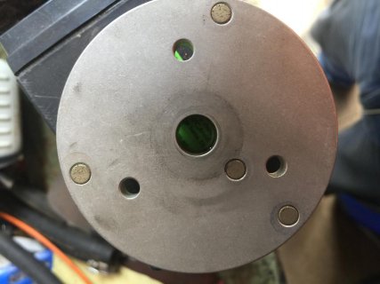
This distributor is triggered by this rotating disk 87F24E4D-F612-4B1E-9ED1-CD553A389761.jpgwith 3 magnets at 120 degrees and a single magnet at TDC above its Circuit board.
87F24E4D-F612-4B1E-9ED1-CD553A389761.jpg

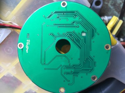
The circuit board looks like this on the side facing the magnets
CE12FC77-81D2-4CC2-A0D7-8DBD14E77966.jpg

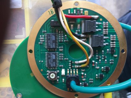
The bottom side away from the magnets
7310FF30-430B-460B-9248-7B20C55EFB1A.jpg
 
Status
Not open for further replies.
Back
Top