I'd like to add an DB9 (RS232) port on top of the Teensy 3.2. Does anybody know if an empty "shield" kit is available, or what size PCB I would need to stick on the top of the Teensy?
Also, are there any enclosures for a Teensy 3.2? Is it safe to just use heatshrink/wrap to prevent the PCB from touching anything and shorting out?
The Teensy is 0.7" x 1.4".
One prototyping board that I like to use for the Teensy is the 1x2" prototyping board from Azzy's Electronics (who makes various sized prototyping boards). You can attach all of the pins of the Teensy to the board, and you have a 3x18 row down the middle to attach plugs and such in the layout for the plug. It is just slightly bigger than the Teensy:
I also like the Adafruit small mint tin board. It has two power rails running down the middle, and a little area on each end to stick things. It also has 4 screw holes that you can use to attach it to a platform:
Another interesting one is the DIP (28-pin) board that has two sets of 15x3 rows with 4 power rails running down the inside and outside. Each end has a 10x3 area for mounting things, and some break away screw holes for mounting:
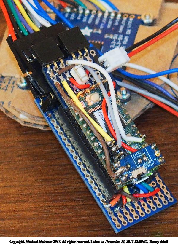
Here is one of my Teensys using the last board (DIP 28-pin). Note, this uses the variant of the board that doesn't have the screw holes in it:
In terms of protecting the underneath of the Teensy from shorts, I sometimes put a hook & eye strip (i.e. velcro [tm]) strip underneath the platform, and it allows me to attach the Teensy without having to need screws. I would suspect using heatshrink might be a problem if the heat gun causes any of the solder to melt and join together. Other times, I use nylon screws to mount the prototyping board higher, so the bottom doesn't touch anything.
I generally solder female headers on the boards, and put male headers on the Teensy. That way I can move the Teensy to another setup. Generally I have the wires soldered to the board, and not to the Teensy. For example, in the image I posted, the front 10x3 area brings out the i2c pins, and A9/A8. The back of the board that you can't see brings out the SPI related pins (those are the wires sticking out of the back of the Teensy). The back of the Teensy has a small board that brings out A10/A11 and a digital pin (3) for use with analog/digital inputs such as a joystack.