High sampling rate measurement for weak electrish fish

Status
Not open for further replies.

solidhfm

Member
Hello you lovely people!

I want to measure the EOD's of weak electric fish. The pulses they send out have a duration of about 1ms and are weak(mV range).
For this project i need a sample rate of at least 100kHz with a resolution of at least 12bit. I spent the last week to gather information
and now i'm at a point where i don't know how i should proceed or if i have the right direction. My plan is to take a teensy 3.5/3.6
and save the measurements directly(10min) on a SD card. I dont have problems with the code but rather with the hardware. I tried to accomplish
the plan with an Arduino Mega 2560 and an external 16bit ADC(ADS1115) but realized that i cant even scratch the sample rate of 100ksps.
Questions:
-can i accomplish this project with a teensy ?
-can i accomplish this with an external ADC if so do you have any tipps wich to use ?
for this i thought about something like http://www.ti.com/product/ads8331 ... do i only need to solder them on a pcb and i'm ready to go ?

I'm completly new in this field so i'm greatful for every advice in advance!

Best regards!
 
100kHz sample rate at 12bit can easily be done with the internal ADC of the Teensy 3.2, 3.5, 3.6 using DMA to write the data into a (ring) buffer before you write the content in blocks on the SD card (which is much slower).
 
100kHz sample rate at 12bit can easily be done with the internal ADC of the Teensy 3.2, 3.5, 3.6 using DMA to write the data into a (ring) buffer before you write the content in blocks on the SD card (which is much slower).

Thank you very much! I'll try the Teensy then.
 
Ok here is my plan:

I want to use a Teensy 3.6. The EOD of the fish has a duration of 0.6-1ms and a range of about 0.6V.
With the 12bit resolution (1bit = 3.3V/2^12 = 0.8mV) i wont even need to amplify the voltage or should i ?
The sampling rate of 100kHz - 200kHz is enough i guess and with the method of using DMA to a ring buffer will do the job with the onboard SD.
BUT!
i need an opamp because of the unipolar ADC could the guide me in the right direction?
and to block the noise i want to use a bandpass filter ... can i do this on the software side or should i build a circuit for this?
the last thing is the 3.3V operationrange ... i should use a zener am i right ?

Thank you for any advice!
 
Using the internal 1.2V reference for the ADC will give better resolution in your case. And if your signals are bipolar, yes, you'd need an op-amp or at least a njfet (source-follower) as a bias shifter.
 
Using the internal 1.2V reference for the ADC will give better resolution in your case. And if your signals are bipolar, yes, you'd need an op-amp or at least a njfet (source-follower) as a bias shifter.

Maybe if he uses one differential input of teensy it migth work without preamp or bias shifter? Also better resolution 16 bit achievable. Regarding reference 1.2V I agree.
A closer look at pedvides ADC library might be usefull.
 
In differential mode, you might set the ADC to 16bit resolution, but according to the data sheet, only 13bit (12bit as usual plus the sign bit) will be meaningful. The rest is noise.
 
The internal 1.2V is a very good idea! Thank you for that!
Regarding the opamp ... never used one before

http://www.ti.com/lit/ds/symlink/op07d.pdf will this do ?

BUT i still dont get what to put where ... if i set 0.6V on IN- and my analog input on IN+
will the output be 0V at 0.6V and -0.6V at 0V(difference between IN- and IN+) ?
This is still unclear to me :/ i'm a biologist and never ever worked with something like this before.
 
I want to measure the EOD's of weak electric fish. The pulses they send out have a duration of about 1ms and are weak(mV range).

I'm not familiar with this type of signal/sensor. Is any more info available?

For connection directly to Teensy's ADC pins (without an opamp), details like low impedance are important.
 
The EOD's(electric organ discharge) should look like this:

http://mormyrids.myspecies.info/sit...echidnorhynchus_JPS-110_EOD.png?itok=EXlvZ-RF

I dont think the signal was amplified. But instead of buying rather expensive equipment i want to measure the fish with a selfmade option.
Because of the short bursts i need a high sampling rate(therefor the teensy) and because the Teensy has 2 ADCs i could measure on 2 channels too.
But as you can see, the EODs are positive and negativ, thus the opamp for the unipolar teensy adc
 
The graph shows a peak-to-peak amplitude of 1.6V. This is rather optimal for 3.3V (giving 1 bit headroom) than for 0.6V (will overdrive, additional scaling required). Since the signal is relatively short (<= 1ms) you might simplify everything with AC coupling and a fixed DC bias of VCC/2 and a unity gain buffer op-amp.
 
The EOD's(electric organ discharge) should look like this:

Knowing the expected voltage is good, but this graph tells us nothing about the signal's impedance and ground, which are important details for designing the opamp circuitry.

If the sensor is electrically "floating", then things can be done which aren't possible if the signal is referenced to earth ground.

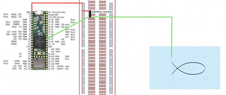
I wanted to ground the analog signal via the breadboard on the teesny ground with a 10kOhm-resistor to get rid of the floating.

project2.jpg

something like this.
 
you never really said, how you pick up the EOD?
not by putting a wire into the water?
or did I miss some info?
 
Sorry! I'm using carbon rod electrodes.

Ok, it seems you are only using an electrode (I used the term wire with the meaning conductor)
But you need a potential difference to be measured, right?
so where is the reference electrode?

From what I know fro this type of short pulses they are unable to generate a lot of current. So you need your two electrodes to be connected first to an instrumentation amplifier before connecting to any ADC (teensy included).

So what is exactly your experimental setup?

Edit:
As you placed earlier a picture of this blog http://mormyrids.myspecies.info/en/node/484
I guess you are also following his advice on how to interface the electrodes with the ADC / Teensy
 
Last edited:
Ok, it seems you are only using an electrode (I used the term wire with the meaning conductor)
But you need a potential difference to be measured, right?
so where is the reference electrode?

From what I know fro this type of short pulses they are unable to generate a lot of current. So you need your two electrodes to be connected first to an instrumentation amplifier before connecting to any ADC (teensy included).

So what is exactly your experimental setup?

Edit:
As you placed earlier a picture of this blog http://mormyrids.myspecies.info/en/node/484
I guess you are also following his advice on how to interface the electrodes with the ADC / Teensy

Yes there are two plans:

A setup for experimental purpose with a tube and two electrodes(head and tail). The teensy has two ADCs so i can use two channels with a high SPS-rate.
The second would be a control setup in the main tank with two or four electrodes.

We have a field-amplifier with a low- and highpass-filter but i wasn't sure if we really need to amplify the signal and there is still the 3.3V cap of the 3.6.
But i dont think the field-amplifier can upset the signal to be positiv thus the opamp. Isn't the 3.3V connector on the teensy 3.6 my reference for the electrodes ?
 
Yes there are two plans:

A setup for experimental purpose with a tube and two electrodes(head and tail). The teensy has two ADCs so i can use two channels with a high SPS-rate.
We have a field-amplifier with a low- and highpass-filter but i wasn't sure if we really need to amplify the signal and there is still the 3.3V cap of the 3.6.
But i dont think the field-amplifier can upset the signal to be positiv thus the opamp. Isn't the 3.3V connector on the teensy 3.6 my reference for the electrodes ?

I may be wrong, but IMO you should first convert the high impedance signal (high voltage-low current) into a low impedance signal (same voltage, but higher current) so you can sample the signal at the desired high sampling rate.

So, it is not about signal amplification but about impedance transformation.

Further, as done in the reference blog and all other cases I have seen on this subject (I did some reading), I would place the two voltages into a differential amplifier and use only one ADC to get the voltage difference. The instrumentation amplifiers on the market are designed exactly for this purpose.

I you wanted to do the difference digitally, then you need still a common ground for the two ADCs to work if used as single ended ADCs.

However, I understand that the teensy ADC can be used as in differential mode, then you only need two voltage following op-amps (unit gain) to boost the available current for the ADC.
 
So i found out that my field-amp can measure the voltage difference between two inputs, has a gain, a low-pass and a high-pass filter, all to a single output.
Would be perfect i guess. The only thing that i need now, would be a zener to keep my 3.3V in check am i right ?
 
So i found out that my field-amp can measure the voltage difference between two inputs, has a gain, a low-pass and a high-pass filter, all to a single output.
Would be perfect i guess. The only thing that i need now, would be a zener to keep my 3.3V in check am i right ?
check if you can limit the output of your field-amp to either 0-3V or +- 1.5V.
if it is, say +- 12V, then, IMO, a simple voltage divider may be suitable.
 
So after i finally got my Teensy 3.6 and soldered it on a breakoutboard(was quite hard) i started reading into DMA, ADC, Buffer etc..
Everything is new to me and kinda hard to understand but i tried all the examples and this is what i have sofar:

Code:
#include "ADC.h"
#include "RingBufferDMA.h"
#include "SdFat.h"


//Prä
//---------------------------------------------------------------------------------
const int readPin = A9; //Pin for reading
ADC *adc = new ADC(); // adc object;
const uint8_t buffer_size = 8; //DMA-buffersize
DMAMEM static volatile int16_t __attribute__((aligned(buffer_size+0))) buffer[buffer_size];
RingBufferDMA *dmaBuffer = new RingBufferDMA(buffer, buffer_size, ADC_0);
File file; //File for SD-Card
char c=0; //start Var
SdFatSdioEX sdEx; //Setup for SdFat
//---------------------------------------------------------------------------------


//---------------------------------------------------------------------------------

void setup() 
{
  Serial.begin(250000);

  //ADC
  adc->setResolution(12); //12Bit Resolution
  adc->setAveraging(1); //still dont really know what this is
  adc->setSamplingSpeed(ADC_SAMPLING_SPEED::MED_SPEED, ADC_0); //ADC-speed
  adc->setConversionSpeed(ADC_CONVERSION_SPEED::MED_SPEED, ADC_0);

  //DMA
  adc->enableDMA(ADC_0); //enable for ADC-0
  adc->enableInterrupts(ADC_0);

  //SD
  /*
  if (!sdEx.begin()) 
  {
    Serial.println("problem");
  }
  
  // make sdEx the current volume.
  sdEx.chvol();
  
  if (!file.open("Data.bin", O_RDWR | O_CREAT)) 
  {
    errorHalt("open failed");
  }

  file.write(testArray,18);
  file.close();
  */
  Serial.println("Ready");
  Serial.println("Press s to start");
}


void loop() 
{
  if (Serial.available()) {  
    c = Serial.read();
    if(c=='s') {
      dmaBuffer->start(&dmaBuffer_isr); //start the DMA-Ringbuffer i guess
      adc->analogRead(readPin, ADC_0); //give the Buffer input from ADC-0 Pin9
      if (!sdEx.begin()) 
      {
        Serial.println("problem");
      }
  
      // make sdEx the current volume.
      sdEx.chvol();
  
      if (!file.open("Data.txt", O_RDWR | O_CREAT)) 
      {
        errorHalt("open failed");
      }

      file.write(dmaBuffer,dmaBuffer->size());
      file.close();
    
    }
  }
}

//Stuff
//---------------------------------------------------------------------------------
void errorHalt(const char* msg) 
{
    sdEx.errorHalt(msg);
}
uint32_t kHzSdClk() {
  return sdEx.card()->kHzSdClk(); 
}  
void dmaBuffer_isr() 
{
    //digitalWriteFast(LED_BUILTIN, !digitalReadFast(LED_BUILTIN));
    Serial.println("dmaBuffer_isr");
    // update the internal buffer positions
    dmaBuffer->dmaChannel->clearInterrupt();
}
void adc0_isr(void) 
{
    //int t = micros();
    Serial.println("ADC0_ISR"); //Serial.println(t);
    adc->adc0->readSingle(); // clear interrupt
}
void printBuffer() 
{
    Serial.println("Buffer: Address, Value");

    uint8_t i = 0;
    // we can get this info from the dmaBuffer object, even though we should have it already
    volatile int16_t* buffer = dmaBuffer->buffer();
    for (i = 0; i < dmaBuffer->size(); i++) {
        Serial.print(uint32_t(&buffer[i]), HEX);
        Serial.print(", ");
        Serial.println(buffer[i]);
}
}

I tried to set up a DMA-ringbuffer and write it via SdFat on to the SD-Card ... not really working as it should be.
Am i on the right track or realllly far of ? How can i write the DMAbuffer on the SD-Card?
 
So after i finally got my Teensy 3.6 and soldered it on a breakoutboard(was quite hard) i started reading into DMA, ADC, Buffer etc..
Everything is new to me and kinda hard to understand but i tried all the examples and this is what i have sofar:

Error #1: never solder a Teensy if you can use a breadboard. (OK this is void now)

Suggestion :
forget about DMA/SD and simply try to understand ADC (different modes, setups etc) This is easy done on breadboard.
IMPORTANT: use AUDIO software (gui) to setup Acquisition
It is much more powerful than common assumed (e.g. it can do buffering for you)

Step 2: choose SD SW for logging (if no other processing, DMA is not needed)
Step 3: try a simple ADC logger with slow conversion rate (using a poti to change voltage)
Step 4: simulate the EOD on breadboard.
Step 5: speedup acquisition.
 
Status
Not open for further replies.
Back
Top