uNav AHRS

Status
Not open for further replies.
Here's a sketch and a memo that discusses how to verify that a MPU9250 is aligned and producing sensor outputs consistent with a NED body frame (per Brian's library). I wanted to document it for myself, so I could remember how I verified it, so thought it might be helpful to others. Also thought it might help in troubleshooting these various filters to make sure we're getting the same PRY out of each.

Attachment to follow (won't let me attach stuff on my iMac)...
 
Don, if you look in Madgwick's paper it looks like z points up, y points to the left and the x points to nose. Also, if you check out the layout for one of his test setups with for the filter I believe it confirms this: https://storage.googleapis.com/goog...ithm30042010sohm/physical axis alignments.pdf . I would love to get confirmation of this. The axis orientation has always been a challenge. The IMU I have that does not have z-axes aligned are the 9150 and the 9250. I know Kris's code just makes mz negative in the filter.

Right now it, with the current ypr function I have assuming, since Brian swapped the x and y axis, so x points in the +y direction marked on the board the function will return nose up positive, left wing up pos and rotation +to the right. The only filter that doesn't do this is the DCM - I have to adjust the quaternions again. Probably messed it up years ago to begin with.

I think the trick is figuring out what assumptions Mahony and Madgwick need for us to be in sync with Brian's library. Also, I've been assuming they need accel with gravity left in, but it may be that they need gravity components removed first...
Good question. The filter itself normalizes the accel and magnetometer measurements. The ypr function I have uses the direction of gravity to do the calculation for the YPR.


I've put together a cool little sketch that uses Brian's NED MPU9250 and helps to verify that XYZ is what we think it is on the board.
Looking forward to checking this out.
 
Mike,
That might be the trick! ... if Madgwick is using a NWU (North West Up) frame. That frame is rarely used in the aerospace apps that I've been involved with, but not difficult to transform to/from.

It's been a while since I used Winer's code, but I believe he kept the MPU outputs in the frame that they were on the board, where gyro and accel are NED and the mag was something different. So he had to switch terms and change some signs when inputting the sensor values to the filter.

If Madgwick is using NWU, we should be able to do a similar alteration. Wrapping up for day, but will look at it again over next day or two.
 
Mike,
I think your discovery may be correct. I just negated the y and z terms for the Madgwick and I think it's aligned now to yaw pitch and roll...

So it does seem Madgwick is using a NWU convention. Need to put it down for day, but think you may have found the issue!!
 
Mike,
The Madgwick seems to work on the first release of your code (when I input the sensors as NWU), but a sign is off in the second release. I noticed on your second release of the code, the getYawPitchRollRad has the ypr[1] equation negated, and that wasn't there in the first version. So think the sign got changed in the second version.
 
Don
In the second release I changed the gravity calculation (left the original commented since I am still playing) so would get correct results with current sensor axis orientation. I am going back now to negate ay, az and gy and gz. If you negate the sensors then you will probably have to go back to the original ypr function. I thought I would have it checked out before you since you said you were done for the night :)
 
I'm about to take a break myself but I will be back to this. Getting too frustrated that this is not working as easily as I thought. Have a great night.
 
Don - Brian. Just to try and not overload the forum with sketches right now until I got them fully debugged I posted my latest version on dropbox. Here is the link: https://www.dropbox.com/s/xkgrmnxztlf03yb/MPU9250_FiltersV4.zip?dl=0 . Everything is should work with current sensor directions to the sensor. Wanted to keep that fairly constant for now. Anyway I am cooked now.

EDIT> Still haven't forgotten about the quaternion version of the Brian's Kalman filter. I have one question. If I want to say update the gyro variance and biases periodically do I have to a complete filter reset or can I just update x_ with the changes?
 
Mike,
Really nice!! Impressive to see it come together as a pretty complete library!

I took a quick look and MARG 0,1,3, and 5 are all working well here. I see a couple of tweaks needed. I think I can look at it again later today and see if I can fix them. Here's what I see:

MARG 3: PRY signs are correct, but numbers aren't starting out at 0 0 0. Guessing we need to adjust the beta value. I've used Winer's before and it worked well, so I can track that down again.

MARG 4: The PR signs are backwards, Y looks correct

MARG 6: I'm getting a compile error with the #define G line. Wondering if we should rename it something else like gravityConstant. I can come back and try this later.

Really cool!! This will be a fantastic tool to take to the next step... incorporating GPS posn and vel measurements!
 
Don. Thanks for the sanity check. Couldn't sleep so I worked on this - more time spent fixing stupid typos or things I did. I thought I caught everything but never seen all the filters in one spot before. Eventually want to see if will work with other IMU. Have one in mind to test it on :).

UPDATE: Got signs fixed for MARG 4 and the MARG 6 Compile error. Here is the updated file: https://www.dropbox.com/s/zpihrjbdynaxfix/MPU9250_FiltersV5.zip?dl=0
 
Last edited:
Hi Brian. Hope you are still with us. I started working the quaternion version of uNavAHRS again, yes, I am a glutten for punishment. So I decided to start at top and work my way down. I am starting with the quaternions, and it has taken me months to realize that in addition to swapping x and y axes you negated the z axis so accel/gyro is aligned with the magnetometer axes. So where I am now is with a few confirmation type questions and other questions that I hope you don't mind my asking:

1. Your axes rotations seems to align them with what is contained in the Vector Nav App Note AN002 (Quaternion math)?
2. Am assuming you are keeping with the 321 (PRY, or yxz) Euler angle rotation as shown in the paper?
3. In looking at the initialization for _Quat it would seem to confirm item 1, but when I look at your get quaternion function it appears they return the q values in the wrong order
IS:
Code:
  *qw = _Quat(0,0);
  *qi = _Quat(1,0);
  *qj = _Quat(2,0);
  *qk = _Quat(3,0);
Should Be (I think):
Code:
  *qi = _Quat(0,0);
  *qj = _Quat(1,0);
  *qk = _Quat(2,0);
  *qw = _Quat(3,0);
4. If assumptions 2 is correct then should the initialization for the Euler angles be based on the equations 28 and 28 in Freescale App Note AN3461 (Tilt Sensing Using a Three-Axis Accelerometer) and equation 22 in AN4248 which looks like what you are doing although have to satisfy myself on the format you are doing. (Man, you are bringing me back to what I used to do in grad school).
5. Assuming my assumption in 2 and 3 are correct then I think your euler to quat function doesn't match whats in AN002. Not sure yet.

Ok that's about it for now until i get through the rest.

Thanks
Mike
 
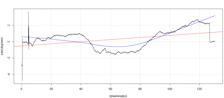
Hi Brian. Still curious about the rotations you have in uNavAHRS but it looks like I resolved one problem I was having where q0 would be reflected as q4. The only thing I changed was in my sketch on how i was calling getquaternion and referencing the values. I made a very simple change and when i went to rerun the sketch the quaternions were aligned correctly. I let the sketch run for a little over two hours with a SRD of 4, and yaw behaved very nicely. I could see the filter correcting the quaternions in Tviewer and had a variation in yaw from -1.5 degrees at it minimum to a maximum of about 2.6 degrees before I decided to rotate the board back 0 just as a check. I will do a plot tomorrow showing the test results.

BTW. please don't take my previous post as criticism I really want to understand what's going on and how you did things. If i didn't do the above i would never have found the problem.
 
Here is the chart.
 

Attachments

  • Capture.PNG
    Capture.PNG
    18.2 KB · Views: 102
Last edited:
while select H matrix like this?

H_ahrs = [ -skew(gn) , 0]
// [0, 0, hn_x , 0]
// Populate accel-based measurement - Upper 3x6
// Negative skew symmetric of the gravity accel vector in NED frame [0, 0, 9.81]
H_ahrs[0][1] = 9.80; H_ahrs[1][0] = -9.80;
// Populate magnetometer - based measurement - Lower 1x6
H_ahrs[3][2] = hn_x;
can you give me some paper?I donot understand this。
 
Hi all,

I ported the uNav Attitude and Heading Reference System (AHRS), which is a 7 state Extended Kalman Filter (EKF) used to estimate attitude and heading from IMU data, to work well as an Arduino library.
https://github.com/bolderflight/uNavAHRS

This particular filter was developed by Jung Soon Jang at Stanford University and was used at the University of Minnesota UAS Research Labs since 2006. It hasn't been used as a primary navigation filter at the University of Minnesota in a long time, the 15 state EKF which include GPS data is used for that, but it provides good estimates of attitude and heading without requiring a GPS. It uses gyro measurements to propagate the state; accelerometers are used as a measurement update on the pitch and roll channels and magnetometers as a measurement update on the yaw channel to constrain drift. Optionally, airspeed measurements may be provided to correct apparent accelerations that can lead to errors in AHRS filters used on air vehicles.

Performance is great on a Teensy 3.6, it takes about 125 us for a time and measurement update. I've included an example of using this filter with the MPU-9250 IMU.

Best,
Brian

H_ahrs = [ -skew(gn) , 0]
// [0, 0, hn_x , 0]
// Populate accel-based measurement - Upper 3x6
// Negative skew symmetric of the gravity accel vector in NED frame [0, 0, 9.81]
H_ahrs[0][1] = 9.80; H_ahrs[1][0] = -9.80;
// Populate magnetometer - based measurement - Lower 1x6
H_ahrs[3][2] = hn_x;
while H matrix like this?I donot understand,can you help me?
 
Mike,
Yesterday was drone work, today i’m tied up with another project. But tues and wed are pretty open so i’ll hit it hard again then. Anxious to try your new version!! Looks like you’ve made even some more progress too!

Don
 
Hi Brian. Hope you are still with us. I started working the quaternion version of uNavAHRS again, yes, I am a glutten for punishment. So I decided to start at top and work my way down. I am starting with the quaternions, and it has taken me months to realize that in addition to swapping x and y axes you negated the z axis so accel/gyro is aligned with the magnetometer axes. So where I am now is with a few confirmation type questions and other questions that I hope you don't mind my asking:

1. Your axes rotations seems to align them with what is contained in the Vector Nav App Note AN002 (Quaternion math)?
2. Am assuming you are keeping with the 321 (PRY, or yxz) Euler angle rotation as shown in the paper?
3. In looking at the initialization for _Quat it would seem to confirm item 1, but when I look at your get quaternion function it appears they return the q values in the wrong order
IS:
Code:
  *qw = _Quat(0,0);
  *qi = _Quat(1,0);
  *qj = _Quat(2,0);
  *qk = _Quat(3,0);
Should Be (I think):
Code:
  *qi = _Quat(0,0);
  *qj = _Quat(1,0);
  *qk = _Quat(2,0);
  *qw = _Quat(3,0);
4. If assumptions 2 is correct then should the initialization for the Euler angles be based on the equations 28 and 28 in Freescale App Note AN3461 (Tilt Sensing Using a Three-Axis Accelerometer) and equation 22 in AN4248 which looks like what you are doing although have to satisfy myself on the format you are doing. (Man, you are bringing me back to what I used to do in grad school).
5. Assuming my assumption in 2 and 3 are correct then I think your euler to quat function doesn't match whats in AN002. Not sure yet.

Ok that's about it for now until i get through the rest.

Thanks
Mike

Still here! And keeping up with the work you and Don are doing; although, I haven't had a chance yet to download the DCM, Madgwick, Mahony, and CF algorithms yet.

1. It shouldn't be aligned with the VectorNav note. They are defining their quaternion such that a 0, 0, 0 Euler orientation would be q(0,0,0,1) and I'm defining it like q(1,0,0,0). I did this because all of the prior UMN filters were derived with that quaternion order as well as many of the research papers I've seen, so it made it quicker for me to compare.
2. Yes, I'm using a 321 Euler angle order.
4. In AN3461, Equation 28 is derived from a 321 Euler angle order. Equation 24 - 26 are from a 321 order. You'll see that the transformation I use for theta and phi, is derived from equation 24. The difference is that I wasn't using normalized accelerations when I derived it, I was simply dividing by 9.807 (i.e. theta would be asinf(ax/9.807)). But in the code, I normalize the accel vector and simply removed the divide by 9.807. Yes, I'm computing yaw in the same way Eq 22 in AN4248 is.

Hope that helps! I'm trying to meet with some of the local experts in navigation estimation this week to discuss quaternion vs DCM vs Euler to help pick a direction and then start expanding the states for GPS integration.
 
H_ahrs = [ -skew(gn) , 0]
// [0, 0, hn_x , 0]
// Populate accel-based measurement - Upper 3x6
// Negative skew symmetric of the gravity accel vector in NED frame [0, 0, 9.81]
H_ahrs[0][1] = 9.80; H_ahrs[1][0] = -9.80;
// Populate magnetometer - based measurement - Lower 1x6
H_ahrs[3][2] = hn_x;
while H matrix like this?I donot understand,can you help me?

I don't see where that came from, it's not in my code.
 
Mike,
Just ran through Ver5, and it looks like the MARG 3 signs are correct, but the pitch and yaw values aren't starting at 0 for me. For MARG 4, the sign on roll and yaw are backwards now. MARG 6 looks great now!

To get the coordinate frame orientations correct, there seems to be two ways to do it:

1) change the signs/axes of the MPU sensor values when we input them to the filter to match what the filter wants, or
2) leave the signs/axes the same when we input them into the filters, but change the signs/order of the quat2Euler conversion terms

I was guessing we would do 1 (kind of like what Winer does with his code), but looks like you chose 2. I'm guessing either works, as long as maybe we keep track of where we're doing the conversions and why, since they're different for each of the filters. What are your and Brian's thoughts?
 
Brian

Hope that helps! I'm trying to meet with some of the local experts in navigation estimation this week to discuss quaternion vs DCM vs Euler to help pick a direction and then start expanding the states for GPS integration.
Yes it does help. The reason I was asking about q0 vs q4 was that q0 and q3 seemed to be swapped. In other words, usually q0 is around 0.9 or better and q3 lower with q1 and q2 much lower. In what I was seeing was that q3 was typically 0.9 and q0 around half that. This is of course with it just sitting on my desk. The other thing I noticed was that on initialization the 0.9 would appear at q3 or q4 then changes. Oh well. Maybe a clue? Thanks more looking at code later.

The run I had the other night was the only one I had that worked reasonably.

Don,
I was guessing we would do 1 (kind of like what Winer does with his code), but looks like you chose 2. I'm guessing either works, as long as maybe we keep track of where we're doing the conversions and why, since they're different for each of the filters.
A couple of things, never could get any of the MARG filters to start exactly at startup. Most of the time they are at around 0.5deg or better. As for DCM (MARG 4) I know, in this case I actually changed a sign in the start up. I did something weird with the quaternions in the DCM filter and I can't for the life of me remember why. Would prefer to leave them same since Brian already puts the coordinates in NED format. His matrix in the IMU filter has az converted to -az which is correct.

Decided to take a break from the filters for a while and work on the new toy I got from Onehorse (his ST microchip imu) that defragster mentioned earlier in this thread.
 
Hi Don

I updated the sketch to correct the issue with DCM and it is consistent with choice 2 above. Here is the link to the updated file: https://www.dropbox.com/s/sr6dcd3nknb88tv/MPU9250_FiltersV6.zip?dl=0

Let me give you a little explanation of choice 2 for this use case. I am familiar with what Kris does in his codes and how he makes the axes adjustments. If you look in the MPU9250 you will see that Brian already has made the axes swaps and changes signs for accel and gyro to match the magnetometer axes orientation. To keep this orientation consistent among the different filters I chose to just adjust the YPR calculation in my geYPR function. This is consistent for all the filters except the version of the DCM filter I am using. Again, for consistency I chose to just adjust the yaw sign within the filter itself. Anyway that was my rational to go the route of choice 2.

Anyway let me know if I missed anything else.

PS I did get Kris's code working on the T3.5 for his STmicro IMU. My intent is to eventually give it a try with the uNavAHRS library on the T3.5.
 
Status
Not open for further replies.
Back
Top