uNav AHRS

Status
Not open for further replies.
Just processing speed; however, the literature recommends using as high of precision as possible for Kalman filters. Trying doubles might be worth a shot, I haven't checked to see if we're hitting any issues that way.

Indeed T_3.6 [& 3.5] does float on native hardware FPU - doubles are done through software so that could be a big perf hit doing frequent number of involved double operations.
 
Downloaded the 4-State, will take a look.

Have still been messing around with the 7-State. Thought I had it working really well until I added a body-2-inertial DCM routine to get the accel values in inertial NED. It would work fine sometimes, but then mysteriously would be way off. What seems to be happening is that when pitch and roll are relatively level, the yaw (and heading) are very stable. But if you introduce roll or pitch, say at 25+ degrees with no change in yaw, sometimes yaw would jump to some high number, like 60 degrees. This was wreaking havoc in the DCM routine.

So think I'll take a break from the 7-State and try to catch up to y'all on the 4-State...

Don
 
Hi Brian

Just loaded up your new version and just a couple of observations out of the box to help in the analysis.
1. When held motionless or turning gently the measured heading tracks almost as the mean of the raw heading.
2. The raw measurement seems to vary about +/- 4 degrees about the mean, about what I was seeing before.
2. Let it run for about 15 minutes and no perceptible drift.
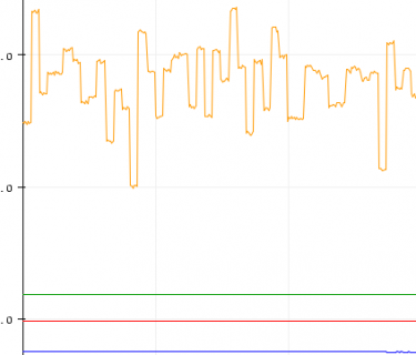
3. Here is the big one. After I put it through some rapid motion, like rolling the dice the raw measured heading is about 10-15 degrees higher than the measured heading from the filter. Here is a screen shot of what I mean:
Capture01.PNG

Thanks for everything you are doing with the Kalman filter. Learning a lot as we go.

Mike
 
Brian,
Got it up and running, looking good thus far. The pitch (theta) in the Quat2Eul will blow up if pitch is raised to 90 degrees. Here's a quick fix I added to the cpp file to prevent this singularity:

/* Transforms quaternion (q[1,0,0,0]) to euler angles (phi, theta, psi) */
Eigen::Matrix<float,3,1> uNav4StateAHRS::Quat2Eul(Eigen::Matrix<float,4,1> q) {
Eigen::Matrix<float,3,1> eul;
float eulTemp;
float asinLimit = 0.998;
eulTemp = -2.0f*q(1,0)*q(3,0)+2.0f*q(0,0)*q(2,0);

// Add check to keep pitch from going singular
if(eulTemp>asinLimit){
eulTemp = asinLimit;
}
else if(eulTemp<-asinLimit){
eulTemp = -asinLimit;
}

eul(0,0) = atan2f(2.0f*q(2,0)*q(3,0)+2.0f*q(0,0)*q(1,0),2.0f*q(0,0)*q(0,0)+2.0f*q(3,0)*q(3,0)-1.0f);
eul(1,0) = asinf(eulTemp);
eul(2,0) = atan2f(2.0f*q(1,0)*q(2,0)+2.0f*q(0,0)*q(3,0),2.0f*q(0,0)*q(0,0)+2.0f*q(1,0)*q(1,0)-1.0f);
return eul;
}
 
Hi Don

Been busy getting Tviewer working. But anyway, went back and did some testing with the Brian last set of changes for the 4state. The heading is right on with respect to my real compass. Tried using the phone but if I put the phone too near the 9250 the raw heading changes to match the measured heading. Was real obvious. The other thing is that I didn't notice the pitch discontinuity it was smooth from -180 to +180. I did see the jumps in roll and yaw when you go around.

Mike
 
I was telling Tim that TelemetryViewer is a bit picky to get installed. Suggest watching the author's video, and reading the youtube comments. I had a heck of a time getting the right version of JRE (32 vs 64 bit I think) installed, but once I got the right one everything clicked.

To get the pitch discontinuity, I was bringing pitch up to 90 degrees, and right when I get close, the program starts printing out all Nan's. But when I add in the discontinuity prevention code, it stays solid for me.

I'm also seeing the yaw drift (or jump) if I "fly" the board around. But heading seems to stay right on.

Will mess around to see if I have better luck with my DCM functioning tonight with the 4-State.

By the way, for TerminalViewer I turn off the Serial.print lines in the cpp file, and then add code to the sketch to print to the serial port every 200000 micros(), i.e. 5Hz. Of course not picking up all the points, but works great for analysis!
 
Attached is the 7 state EKF that I derived. Per the discussion earlier, this one is using doubles instead of floats as a test. The performance isn't bad, for me running a Teensy 3.6 at a CPU of 240 MHz and a MPU-9250 connected over SPI, it takes 1700 us per frame, which includes the time for most of the print statements. The normal caveats apply, this is definitely work in progress and it's meant to run at a rate of 100 Hz with all of the IMU values getting updated at that interval.

I plan on cleaning up this version of the EKF, adding the capability to handle more IMU rates, and add an API around it before updating the github library.

Not sure if I'll keep it double or switch back to float, I'll need to compare output performance and filter timing; especially on processors not as capable as Teensy 3.6.

Any testing data or feedback is really appreciated! Hopefully it's clear and informative how the 4 state EKF gets extended to the 7 state EKF. If I find time, I plan on writing the derivations for each.

Brian

EDIT: the timing doesn't include the data collection time from the MPU-9250, only the filter timing. From previous performance tests, with the MPU-9250 on SPI and a Teensy 3.6, this should be around 25 us.
 

Attachments

  • uNavAHRS.zip
    7.2 KB · Views: 166
Don.
To get the pitch discontinuity, I was bringing pitch up to 90 degrees, and right when I get close, the program starts printing out all Nan's. But when I add in the discontinuity prevention code, it stays solid for me.
Tried to duplicate it but just not seeing the nans for some reason.

By the way, for TerminalViewer I turn off the Serial.print lines in the cpp file, and then add code to the sketch to print to the serial port every 200000 micros(), i.e. 5Hz. Of course not picking up all the points, but works great for analysis!
That's what I am going to do next. Wanted to make sure I understood how Tviewer worked first. I also printed out the sensor statistics and after looking at the numbers. Here they are just in case anyone is interested:
Code:
x_ initialized to:
0.129671196260
-0.022887179136
0.032803583691
-0.990577044764

P_ initialized to:
[ 0.000335812104, 0.000000000000, 0.000000000000, 0.000000000000,  ]
[ 0.000000000000, 0.000000690101, 0.000000000000, 0.000000000000,  ]
[ 0.000000000000, 0.000000000000, 0.000000357381, 0.000000000000,  ]
[ 0.000000000000, 0.000000000000, 0.000000000000, 0.000005804341,  ]

Q_ initialized to:
[ 0.000000386331, 0.000000000000, 0.000000000000,  ]
[ 0.000000000000, 0.000000389652, 0.000000000000,  ]
[ 0.000000000000, 0.000000000000, 0.000000383677,  ]

Ra_ initialized to:
[ 0.000128212938, 0.000000000000, 0.000000000000,  ]
[ 0.000000000000, 0.000069628563, 0.000000000000,  ]
[ 0.000000000000, 0.000000000000, 0.000169827005,  ]

Rh_ initialized to:
[ 0.535564614270, 0.000000000000, 0.000000000000,  ]
[ 0.000000000000, 0.461290813601, 0.000000000000,  ]
[ 0.000000000000, 0.000000000000, 0.541210331143,  ]

The prints are inside the library for only one reason. Could figure out how to pass the Eigen matrix to another function. Oh well.

I'm also seeing the yaw drift (or jump) if I "fly" the board around. But heading seems to stay right on.
The only time I see the jump in yaw or heading is during transition from say 1deg to 359 and vice versa. When I fly the board around I don't see the drifting, the heading stays steady. I see changes in the raw heading values (yh_). But when I look at the gyro min-max values do change a little bit. like 0.0015 to 0.0025 for gx. Funny that we are getting different behaviors. I am using his non-Watson version for testing. Oh. I should mention that I a changed from floats to doubles.

Brian. Will give the 7-state tomorrow sometime want to play around with the 4-state a little longer before transitioning. You know you can get a paper or two out of all this work - great for class work as well if you are teaching :).

Mike
 
Mike,
That is curious that your pitch values don’t blow up. My only guess is that asin needs to stay within plus or minus 1, and maybe my float values jump out of that range vs your double values.

Guess i’ll try out out the new 7-State as well.

On the 4-state update step, why not just combine the accel and mag measurements into one step (similar to the Watson paper)? I guess the advantage of two steps is that it allows you to easily just update for one if only one is present.

Great stuff!!
 
Brian. Will give the 7-state tomorrow sometime want to play around with the 4-state a little longer before transitioning. You know you can get a paper or two out of all this work - great for class work as well if you are teaching :).

Thanks! I co-taught a course on navigation filters for a few years and am planning on doing something with all this code. I'm thinking derivations alongside examples that can be run to demonstrate the theory. Break it up into time updates, then looking into the measurement update, etc. Hopefully building from the 4 state linear KF to the 4 state and 7 state EKF to something close to the 15 state EKF, which is typically what students were designing and flight testing in the class. We'll see, I'm still chewing on exactly how I would present everything and what medium (website, white paper, etc.)
 
On the 4-state update step, why not just combine the accel and mag measurements into one step (similar to the Watson paper)? I guess the advantage of two steps is that it allows you to easily just update for one if only one is present.

Funny, I combined it into a single step in the 7 state version of the EKF. I still need to work through whether one approach would be more technically correct than the other.
 
Thanks! I co-taught a course on navigation filters for a few years and am planning on doing something with all this code....We'll see, I'm still chewing on exactly how I would present everything and what medium (website, white paper, etc.)
It would be a waste not to do it. One of the best approaches I have seen was in a presentation where the theory is presented first then it is broken down step by step with the equivalent code next to next to it with possibly what some of the data is associated with some of the steps. That is why I printed out the covariance matrices and then compared to that to previous data as well as what it was defined in the code and then things started clicking.

Good luck. Keep us posted :)
 
Brian,
Both work, I've implemented filters both ways. What needs to be watched out for is if P is reduced too much with each step then P can cause the filter to think it's doing better than it is or to reduce the impact of the measurements on the solution.
 
Hi Brian

A quick question if I may. Just want to be sure that _Quat(0 to 3) corresponds to qw, q1, q2, q3 respectively. I am assuming it does but if I have a 50 50 chance I always pick the wrong one

Thanks
Mike
 
Hi Brian

A quick question if I may. Just want to be sure that _Quat(0 to 3) corresponds to qw, q1, q2, q3 respectively. I am assuming it does but if I have a 50 50 chance I always pick the wrong one

Thanks
Mike

Yes, that's correct.
 
Thanks Brian. Found some time and was just working on calls for the data from library. You saved me time.

Mike

Question: is there an easy way to the quats without individual calls?

Just added this function - hope it works:
Code:
void uNavAHRS::getQ(float q0, float q1, float q2, float q3) {
  q0 = _Quat(0,0);
  q1 = _Quat(1,0);
  q2 = _Quat(2,0);
  q3 = _Quat(3,0);
  
}
 
Last edited:
Thanks Brian. Found some time and was just working on calls for the data from library. You saved me time.

Mike

Question: is there an easy way to the quats without individual calls?

Just added this function - hope it works:
Code:
float uNavAHRS::getQ(float q0, float q1, float q2, float q3) {
  q0 _Quat(0,0);
  q1 _Quat(1,0);
  q2 _Quat(2,0);
  q3 _Quat(3,0);
}

I just pushed a function to GitHub that should work.
 
Brian,
Got the 7-State up and running. Are you all seeing drift in yaw and heading?

I’m on the I2C bus, will try switching over to SPI bus later today or tonight too.

Don
 
Hi Brian.

Thanks for the function. By the way was doing some testing on the pre-GitHub release and yes I did see drift with yaw. Also, if I moved it rapidly and put it back to its approximate starting place the heading was way off from starting position by about 50degs. Don't know if you or Don saw this.
Mike
 
Yes Mike, same thing I'm seeing. Downloading the new release now and getting ready to see if I can switch to SPI bus.
Don
 
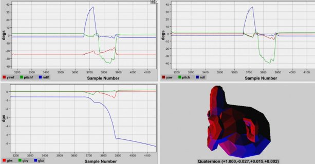
Running the filter at 100hz (srd = 9) and after some rapid movement it looks like I loose the gyro's, here is a screen shot:
Capture.jpg
The only way to recover is resetting the Teensy. I have another 9250 so I can give that a try with using SPI. Running the filter at 250Hz (srd = 4) I get blips in angles just about corresponding to blips in gbx. Strange stuff.

Oh. The angles in the upper right quadrant correspond to this formulation for the angles:
Code:
void getYawPitchRollDeg() {
  //float q[4]; // quaternion
  //float val[11];
  float grx, gry, grz; // estimated gravity direction
  //getQ(q, val);
  
  grx = 2 * (qf[0]*qf[3] - qf[0]*qf[2]);
  gry = 2 * (qf[0]*qf[1] + qf[2]*qf[3]);
  grz = qf[0]*qf[0] - qf[1]*qf[1] - qf[2]*qf[2] + qf[3]*qf[3];
  
  ypr[0] = (180/PI) * atan2f(2 * qf[1] * qf[2] - 2 * qf[0] * qf[3], 2 * qf[0]*qf[0] + 2 * qf[1] * qf[1] - 1);
  ypr[1] = -(180/PI) * atanf(grx / sqrt(gry*gry + grz*grz));
  ypr[2] = (180/PI) * atanf(gry / sqrt(grx*grx + grz*grz));
}
 
Tried to follow the Teensy suggestions on connecting the SPI to the Sparkfun MPU9250, but not working. Here's what I've tried (assuming MOSI is SDA, MISO is AD0, SCK is SCL, SS is CS:

SparkFun9250 Teensy3.6
VCC 3.3V
GND GND
SDA 11
SCL 13
INT 1
CS 10
AD0/SD0 12
VDDIO empty

Any suggestions appreciated!

...back to I2C for now...

Don
 
Don,

Connections look like. The only thing is VDDIO, I know on my EMSENSR-9250 I have to connect that to 3.3v to work. Just checked the sparkfun page and it looks like you may have to that also... From what I read the also already have ad0 hooked up to another pin - really set up for i2c I think. Check the links and schematic.

https://forum.sparkfun.com/viewtopic.php?t=44635&user_select=41947

https://media.digikey.com/pdf/Data Sheets/Sparkfun PDFs/MPU-9250_HookupGuide_Web.pdf (check the presoldered jumpers)

UPDATE: Don, took a look at the schematic. Looks like VDDIO and VDD are connected with the SJ1 jumper by default so no changes needed there. AD0/SD0 is prejumpered to ground with the SJ2 jumper so the connection at the board is open. To get the connection you have to change the solder jumper from ground to AD0. Easier to get another breakout board from Amazon for SPI.

Mike
 
Last edited:
Status
Not open for further replies.
Back
Top