Teensy to drive MOSFETS, will these work?

Status
Not open for further replies.

KrisKasprzak

Well-known member
all,

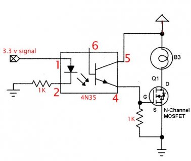
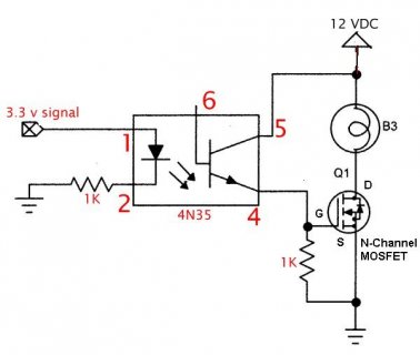
I need to turn 18 amps DC @12 V on or off and would like use a MOSFET--basically a simple switch. I've got a few of these and *think* they will work, but digitalWrite() only outputs 3.3 volts but is above the Vgs threshold.

Also, i was going to mount the on the copper side of my PCB and use 4 or so square inches to cool them--not really sure how to compute heat sink requirements--and surely don't trust my calculation. I'm a former mechanical engineer and I'm out of my area.

A link to the mosfet datasheet.

https://www.infineon.com/dgdl/IPP055N03L_rev1.04.pdf?fileId=db3a30432313ff5e01239ec9d89070ad

Thanks in advance.

Kris
 
If the datasheet you provided is the Mosfet you have then you can drive it with 3.3V. Doing it with the Teensy is probably not the safest thing you can do thou. I would use either a logic buffer IC, a smaller Fet / BJT or an optocoupler. Most of these options will allow you to drive the Mosfet with 5V or up to 12V.

The spec does not list the internal resistance of the Fet at 3.3V but they do list 4.5V and 10V on the gate. At 4.5V the RDSon of the fet is 0.0078R @ 30A. So if you drive 18A you will have .... 18A^2 * 0.0078R = 2.53Watts of heat to dissipate. The same math works for 10V, based on the graph provided you will probably see around 0.05R if you use 3.3V, which would make the Fet very hot.

The other half of the heat equation is how fast you turn the Fet on and off. In the case of the Mosfet you listed from the datasheet the Qgs is very small so even with a large gate resistor it should turn on in less than 100nS.

If we assume 2.5Watts of dissipation using a 5V gate voltage we can look at the thermal characteristics and get an idea of what we will see. According to the datasheet if we have a 6cm^2 pad of copper we get an RthJA of 40K/W. With a Junction to Ambient of 40C/W we will see 100C temperature rise over ambient with 3 watts of dissipation. So in a 25C room the junction temperature would be 125C, which is hot but within safe spec, if the ambient temperature increases 25C then it may not be healthy to the Fet. Gluing a heatsink onto the chip may help to reduce temperatures.
 
thanks Donziboy2.

I will drive the MOSFET on for 90 min then off, no PWM. I found an opto schematic on the web but i don't know if my pin connection for the opt (4N35) is correct (namely 12 v on the base) and my resistor values. Driving the mosfet with 12 V should lower my on state resistance and lower the temp.

Mind checking my work?

opto-MOSFET.jpg


PS do you own a Donzi (boat?)
 
actually i think i leave pin 6 unconnected, correct? and it looks like there is not power to be supplied to the 4N35

opto-MOSFET.jpg
 

Attachments

  • opto-MOSFET.jpg
    opto-MOSFET.jpg
    28.3 KB · Views: 148
  • opto-MOSFET.jpg
    opto-MOSFET.jpg
    29 KB · Views: 166
Last edited:
Yes it appears that the base of the opto transistor is provided for certain cases but is not needed in this case. The LED inside the opto provides the energy needed to power the transistor when current passes through the LED.

The 3.3V side will draw around 2mA. On the right side the gate pulldown resistor in that picture needs to be a higher value, normally 10K. Your not driving the opto very hard so using a low value resistor will actually cause the voltage at the gate to be reduced. Remember the current output is proportional to the input, I think in the case of the 4N35 its 50-100% minimum depending on temperature. So worst case your output current is half your input (3mA / 2) * 1000R = 1.5V at the gate. You can always reduce the limiting resistor on the 3.3V side(maximum with the opto would be around 250R). Just don't try to pull to much current from the Teensy logic pins (9mA recommended max).

If your using more then 1 mosfet add a separate resistor from pin 4 to each gate. 50-100R should be ok if your not PWMing. Mosfets have a bad habit of not turning on at the exact same time using the exact same voltage, to help alleviate that you have to provide separate gate resistors.

Breadboards are your friend, so if you have one give everything a try before you commit to soldering something up only to have to de-solder things to fix something.
 
Status
Not open for further replies.
Back
Top