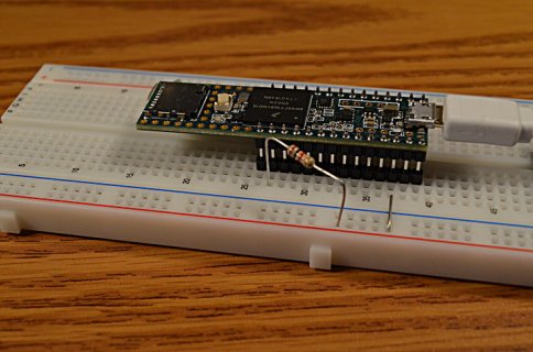
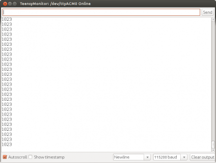
Hey folks, I built a 4 button circuit as per https://github.com/dxinteractive/AnalogMultiButton, essentially to read the four pushbuttons through a single analog pin. Now, I built this on the Mega, and got steady 1023 readings while no button was pressed - I believe this is the expected behavior - the number would change depending on which button I was pressing. Fine.
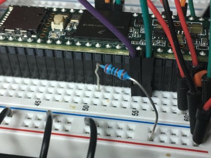
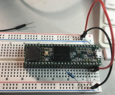
Now I've attached it to the Teensy 3.6 (image attached)
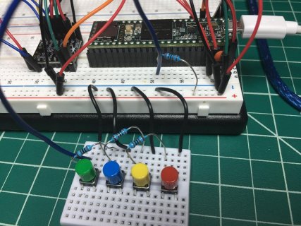
and I'm getting very noisy readings from A0 with no buttons pressed. I've even tried running a 3.3v line directly to the A0 pin to see if I'd get steady 1023 then.. Nope.
Here's what I'm seeing:
and here's the code - essentially the example code, with a button added.
Why am I getting such different behavior between the two platforms? and more importantly.. how can i fix this so I can get steady and reliable feedback from the analog pin? My understanding is that the analog pin should be giving me 0 - 1023 depending the voltage at the pin - 0v to 3.3v. Is this correct?
Thanks...
Now I've attached it to the Teensy 3.6 (image attached)

and I'm getting very noisy readings from A0 with no buttons pressed. I've even tried running a 3.3v line directly to the A0 pin to see if I'd get steady 1023 then.. Nope.
Here's what I'm seeing:
Code:
803
804
820
806
818
812
825
814
795
794
804
819
800
805
819
808
821
816
815
803
817
793
822
806
809
807
782
804
805
and here's the code - essentially the example code, with a button added.
Code:
// include the AnalogMultiButton library#include <AnalogMultiButton.h>


// define the pin you want to use
const int BUTTONS_PIN = A0;


// set how many buttons you have connected
const int BUTTONS_TOTAL = 4;


// find out what the value of analogRead is when you press each of your buttons and put them in this array
// you can find this out by putting Serial.println(analogRead(BUTTONS_PIN)); in your loop() and opening the serial monitor to see the values
// make sure they are in order of smallest to largest
const int BUTTONS_VALUES[BUTTONS_TOTAL] = {1, 962, 510,612};


// you can also define constants for each of your buttons, which makes your code easier to read
// define these in the same order as the numbers in your BUTTONS_VALUES array, so whichever button has the smallest analogRead() number should come first
const int BUTTON_BLUE = 0;
const int BUTTON_YELLOW = 1;
const int BUTTON_GREEN = 2;
const int BUTTON_RED = 3;


// make an AnalogMultiButton object, pass in the pin, total and values array
AnalogMultiButton buttons(BUTTONS_PIN, BUTTONS_TOTAL, BUTTONS_VALUES);


// pass a fourth parameter to set the debounce time in milliseconds
// this defaults to 20 and can be increased if you're working with particularly bouncy buttons


void setup() {
  // begin serial so we can see which buttons are being pressed through the serial monitor
  Serial.begin(115200);
}


void loop() {


  // update the AnalogMultiButton object every loop
  buttons.update();
  Serial.println(analogRead(BUTTONS_PIN));
  // check if BUTTON_RED is pressed
  if(buttons.isPressed(BUTTON_RED))
  {
    // Serial.println("Button red is pressed");
  } else {
    // Serial.println("Button red is not pressed");
  }


  // check if BUTTON_GREEN has just been pressed this update
  if(buttons.onPress(BUTTON_GREEN))
  {
    Serial.println("Green has been pressed");
  }


// check if BUTTON_YELLOW has just been pressed this update
  if(buttons.onPress(BUTTON_YELLOW))
  {
    Serial.println("Yellow has been pressed");
  }
  // check if BUTTON_GREEN has just been released this update
  if(buttons.onRelease(BUTTON_GREEN))
  {
    Serial.println("Green has been released");
  }


  // do this if BUTTON_BLUE has been released
  if(buttons.onRelease(BUTTON_BLUE))
  {
    Serial.println("Blue has been released");
  }


  // do this once if BUTTON_BLUE has been held for 1 second
  if(buttons.onPressAfter(BUTTON_BLUE, 1000))
  {
    Serial.println("Blue has been down for 1 second");
  }


  // do this contantly if BUTTON_GREEN has been held down for less than a second
  if(buttons.isPressedBefore(BUTTON_GREEN, 1000))
  {
    Serial.print("Green is held for ");
    Serial.print(buttons.getPressDuration());
    Serial.println(" ms");
  }


  // do this contantly if BUTTON_RED has been held down for more than a second
  if(buttons.isPressedAfter(BUTTON_RED, 1000))
  {
    Serial.print("Red is held for ");
    Serial.print(buttons.getPressDuration());
    Serial.println(" ms");
  }


  // do this if BUTTON_BLUE was released, and it was held for 1 second or less
  if(buttons.onReleaseBefore(BUTTON_BLUE, 1000))
  {
    Serial.println("Blue has been released after less than 1 second of pressing");
    Serial.print("Blue was held for ");
    Serial.print(buttons.getLastReleasePressDuration());
    Serial.println(" ms");
  }


  // do this if BUTTON_BLUE was released, and it was held for 2 seconds or more
  if(buttons.onReleaseAfter(BUTTON_BLUE, 2000))
  {
    Serial.println("Blue has been released after at least 2 seconds of pressing");
    Serial.print("Blue was held for ");
    Serial.print(buttons.getLastReleasePressDuration());
    Serial.println(" ms");
  }


  //
  // More examples:
  //
  // do this once when BUTTON_BLUE is pressed, and again after 1 second
  // if(buttons.onPressAndAfter(BUTTON_BLUE, 1000)) {}
  //
  // do this once if BUTTON_BLUE is held for 1 second, and again every 0.5 seconds after that
  // if(buttons.onPressAfter(BUTTON_BLUE, 1000, 500)) {}
  //
  // do this once when BUTTON_BLUE is pressed, and again after 1 second, and again every 0.5 seconds after that
  // useful for cursors or scrolling through menu items
  // if(buttons.onPressAndAfter(BUTTON_BLUE, 1000, 500)) {}
  //


  delay(10);
}
Why am I getting such different behavior between the two platforms? and more importantly.. how can i fix this so I can get steady and reliable feedback from the analog pin? My understanding is that the analog pin should be giving me 0 - 1023 depending the voltage at the pin - 0v to 3.3v. Is this correct?
Thanks...


