How to wire membrane potentiometer and other sensors for a MIDI controller

Status
Not open for further replies.

nicnut

Well-known member
Hi,

This is my first project with a Teensy so please excuse my ignorance. I have a Teensy 3.6. I have made many MIDI controllers before using an Arduino Mega so I am familiar with the process, but I have never used a Teensy before.

For now I am trying to use a potentiometer on Analog input 0, a Membrane Potentiometer on Analog input 1` and another Potentiometer on Analog input 2. (nothing is wired to Analog input 3 at the moment, but it's in the code).

I also have 16 button switches in there, and they all work fine.

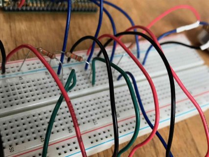
The issue I am having is that I can't get the full range out of the Membrane Potentiometer. I have one wire going to 3.3V, one to Ground and one to the Analog pin. There is a resistor between the Analog pin and Ground. I am doing this on a breadboard to figure it out.

For the resistor used with this Membrane Potentiometer, if I use a 220 Ohms resistor the sensor only goes up to 82 ( in midi control change value) at the max, but when I am not touching the sensor it is at 0 (which is good). If I use a 3.3K resistor it goes up to 123 at the max and I get a solid 0 when not touching it. If I use a 4.7 K ohms resistor the sensor goes up to 124 at max, but sort of fluctuates between 0 and 1 when I'm not touching it (which is bad), and the pots on A0 and A2, who should be at 0, go to 1 when I touch the membrane potentiometer, so it is affecting the neighboring sensors.

Ideally, I would like this membrane potentiometer to go to 127 at the max, be at 0 when I am not touching it, and not affect the neighboring sensors.

Is there a way to do this? Should I add some decoupling caps in there? Is there something I can add in the code? Is there a better way to wire this?

I am also doing this with an FSR (force sensitive resistor) and getting the same problem. Hopefully there is a way around this.

The code I am using is a combination of the example code from the "AnalogControlChange" example and the "Buttons" example under USBMidi.

I have a question about this code too. Why is the Analog read number divided by 8? Like in this line of code:

int n0 = analogRead(A0) / 8;

Thank you in advance for your help. Hopefully there is a solution.


Code:
/* USB MIDI AnalogControlChange Example

   You must select MIDI from the "Tools > USB Type" menu
   http://www.pjrc.com/teensy/td_midi.html

   This example code is in the public domain.
*/

#include <Bounce.h>

// the MIDI channel number to send messages
const int channel = 1;

// the MIDI continuous controller for each analog input
const int controllerA0 = 1; //  control change 1
const int controllerA1 = 2; //control change 2
const int controllerA2 = 3; //control change 3
const int controllerA3 = 4; // control change 4
const int controllerA14 = 14; // control change 15
const int controllerA15 = 15; // control change 15
const int controllerA16 = 16; // control change 16
const int controllerA17 = 17;
const int controllerA18 = 18;
const int controllerA19 = 19;
const int controllerA20 = 20;
const int controllerA21 = 21;
const int controllerA22 = 22;
const int controllerA23 = 23;
const int controllerA24 = 24;
const int controllerA25 = 25;
const int controllerA26 = 26;
const int controllerA27 = 27;
const int controllerA28 = 28;
const int controllerA29 = 29;
const int controllerA30 = 30;

// Create Bounce objects for each button.  The Bounce object
// automatically deals with contact chatter or "bounce", and
// it makes detecting changes very simple.
Bounce button0 = Bounce(0, 5);
Bounce button1 = Bounce(1, 5);  // 5 = 5 ms debounce time
Bounce button2 = Bounce(2, 5);  // which is appropriate for good
Bounce button3 = Bounce(3, 5);  // quality mechanical pushbuttons
Bounce button4 = Bounce(4, 5);
Bounce button5 = Bounce(5, 5);  // if a button is too "sensitive"
Bounce button6 = Bounce(6, 5);  // to rapid touch, you can
Bounce button7 = Bounce(7, 5);  // increase this time.
Bounce button8 = Bounce(8, 5);
Bounce button9 = Bounce(9, 5);
Bounce button10 = Bounce(10, 5);
Bounce button11 = Bounce(11, 5);
Bounce button12 = Bounce(12, 5);  // goes out of order because other pins double as analog inputs

Bounce button24 = Bounce(24, 5);
Bounce button25 = Bounce(25, 5);
Bounce button26 = Bounce(26, 5);
Bounce button27 = Bounce(27, 5);

void setup() {

  pinMode(0, INPUT_PULLUP);   // for button swithces
  pinMode(1, INPUT_PULLUP);
  pinMode(2, INPUT_PULLUP);
  pinMode(3, INPUT_PULLUP);
  pinMode(4, INPUT_PULLUP);
  pinMode(5, INPUT_PULLUP);
  pinMode(6, INPUT_PULLUP);
  pinMode(7, INPUT_PULLUP);
  pinMode(8, INPUT_PULLUP);
  pinMode(9, INPUT_PULLUP);
  pinMode(10, INPUT_PULLUP);
  pinMode(11, INPUT_PULLUP);
  pinMode(12, INPUT_PULLUP);
  pinMode(24, INPUT_PULLUP);
  pinMode(25, INPUT_PULLUP);
  pinMode(26, INPUT_PULLUP);
  pinMode(27, INPUT_PULLUP);

}

// store previously sent values, to detect changes
int previousA0 = -1;
int previousA1 = -1;
int previousA2 = -1;
int previousA3 = -1;


elapsedMillis msec = 0;


void loop() {

  {

    button0.update();    //  this button code works, goes from 0 to 127 when pressed
    button1.update();
    button2.update();
    button3.update();
    button4.update();
    button5.update();
    button6.update();
    button7.update();
    button8.update();
    button9.update();
    button10.update();
    button11.update();
    button12.update();
    button24.update();
    button25.update();
    button26.update();
    button27.update();


    if (button0.fallingEdge()) {                               // this deals with reading the button swithces
      usbMIDI.sendControlChange(controllerA14, 127, channel);
    }

    if (button0.risingEdge()) {
      usbMIDI.sendControlChange(controllerA14, 0, channel);
    }

    if (button1.fallingEdge()) {
      usbMIDI.sendControlChange(controllerA15, 127, channel);
    }

    if (button1.risingEdge()) {
      usbMIDI.sendControlChange(controllerA15, 0, channel);
    }

    if (button2.fallingEdge()) {
      usbMIDI.sendControlChange(controllerA16, 127, channel);
    }

    if (button2.risingEdge()) {
      usbMIDI.sendControlChange(controllerA16, 0, channel);
    }

    if (button3.fallingEdge()) {
      usbMIDI.sendControlChange(controllerA17, 127, channel);
    }

    if (button3.risingEdge()) {
      usbMIDI.sendControlChange(controllerA17, 0, channel);
    }

    if (button4.fallingEdge()) {
      usbMIDI.sendControlChange(controllerA18, 127, channel);
    }

    if (button4.risingEdge()) {
      usbMIDI.sendControlChange(controllerA18, 0, channel);
    }

    if (button5.fallingEdge()) {
      usbMIDI.sendControlChange(controllerA19, 127, channel);
    }

    if (button5.risingEdge()) {
      usbMIDI.sendControlChange(controllerA19, 0, channel);
    }

    if (button6.fallingEdge()) {
      usbMIDI.sendControlChange(controllerA20, 127, channel);
    }

    if (button6.risingEdge()) {
      usbMIDI.sendControlChange(controllerA20, 0, channel);
    }

    if (button7.fallingEdge()) {
      usbMIDI.sendControlChange(controllerA21, 127, channel);
    }

    if (button7.risingEdge()) {
      usbMIDI.sendControlChange(controllerA21, 0, channel);
    }

    if (button8.fallingEdge()) {
      usbMIDI.sendControlChange(controllerA22, 127, channel);
    }

    if (button8.risingEdge()) {
      usbMIDI.sendControlChange(controllerA22, 0, channel);
    }

    if (button9.fallingEdge()) {
      usbMIDI.sendControlChange(controllerA23, 127, channel);
    }

    if (button9.risingEdge()) {
      usbMIDI.sendControlChange(controllerA23, 0, channel);
    }

    if (button10.fallingEdge()) {
      usbMIDI.sendControlChange(controllerA24, 127, channel);
    }

    if (button10.risingEdge()) {
      usbMIDI.sendControlChange(controllerA24, 0, channel);
    }

    if (button11.fallingEdge()) {
      usbMIDI.sendControlChange(controllerA25, 127, channel);
    }

    if (button11.risingEdge()) {
      usbMIDI.sendControlChange(controllerA25, 0, channel);
    }

    if (button12.fallingEdge()) {
      usbMIDI.sendControlChange(controllerA26, 127, channel);
    }

    if (button12.risingEdge()) {
      usbMIDI.sendControlChange(controllerA26, 0, channel);
    }

    if (button24.fallingEdge()) {
      usbMIDI.sendControlChange(controllerA27, 127, channel);
    }

    if (button24.risingEdge()) {
      usbMIDI.sendControlChange(controllerA27, 0, channel);
    }

    if (button25.fallingEdge()) {
      usbMIDI.sendControlChange(controllerA28, 127, channel);
    }

    if (button25.risingEdge()) {
      usbMIDI.sendControlChange(controllerA28, 0, channel);
    }

        if (button26.fallingEdge()) {
      usbMIDI.sendControlChange(controllerA29, 127, channel);
    }

    if (button26.risingEdge()) {
      usbMIDI.sendControlChange(controllerA29, 0, channel);
    }

    if (button27.fallingEdge()) {
      usbMIDI.sendControlChange(controllerA30, 127, channel);
    }

    if (button27.risingEdge()) {
      usbMIDI.sendControlChange(controllerA30, 0, channel);
    }


  }


  // only check the analog inputs 50 times per second,
  // to prevent a flood of MIDI messages
  if (msec >= 10) {               //  i changed this value to 10 from 20 for faster updates
    msec = 0;
    int n0 = analogRead(A0) / 8;
    int n1 = analogRead(A1) / 8;
    int n2 = analogRead(A2) / 8;
    int n3 = analogRead(A3) / 8;
    // only transmit MIDI messages if analog input changed
    if (n0 != previousA0) {
      usbMIDI.sendControlChange(controllerA0, n0, channel);
      previousA0 = n0;
    }
    if (n1 != previousA1) {
      usbMIDI.sendControlChange(controllerA1, n1, channel);
      previousA1 = n1;
    }
    if (n2 != previousA2) {
      usbMIDI.sendControlChange(controllerA2, n2, channel);
      previousA2 = n2;
    }
    if (n3 != previousA3) {
      usbMIDI.sendControlChange(controllerA3, n3, channel);
      previousA3 = n3;
    }


  }

  // MIDI Controllers should discard incoming MIDI messages.
  // http://forum.pjrc.com/threads/24179-Teensy-3-Ableton-Analog-CC-causes-midi-crash
  while (usbMIDI.read()) {
    // ignore incoming messages
  }
}
 
With the pots, by their nature you will never get a 0 ohm resistance through them so the fix here is a mixture of code on the input side and signal conditioning, which ties back to the divide by 8 question. The default analog read behavior runs from 0-1024 (10 bit), so the divide by 8 (3 bits) turns the signal into a 7 bit number 0-128, which I think is part of the MIDI standard.

So to get your flex pot working you either us an op amp
https://www.sparkfun.com/products/9456
to boost up the signal (probably not needed in this case because signal looks to be quite reasonable) or re write your code to take something like the 3.3k resistor and multiply by say 1.1 and then check if > 127 and if so clamp at 127. You may also need to look at the curve your resistor makes as you start to press it and do a log or power curve to get half pressure produce about 64. Doing input curves can be tricky but is a useful trick to master.
 
...I have one wire going to 3.3V, one to Ground and one to the Analog pin. There is a resistor between the Analog pin and Ground. I am doing this on a breadboard to figure it out.

The resistor is to stop the pin from floating as the wiper is disconnected from the pot when there is no contact (i.e. pressure).

If the value is too low most of the current will flow thru that resistor and you'll loose resolution from the soft-pot.

The example schematics for this I've seen use a value equal to that of the pot (10K Ohm).

If you're not getting the full range of output (at 10-bit resolution presumably) then you can remap whatever you are getting to 0-127 (instead of just dividing by eight) using your minimum and maximum raw readings.

Code:
      ccOut = map(pinRead,minRead,maxRead,0,127);


You may still have some issues with stability of the analog readings but I'd say this is a start.
 
Hi everyone. Thank you for your replies. I have been doing a lot of testing with various sensors and resistors, and I will tell you what I found out. But first I want to try oddson's suggestion. I'm not sure how I would implement that in my code.

So what you are suggesting is that I change this line of my code:

int n0 = analogRead(A0) / 8;

to your suggestion of this:

ccOut = map(pinRead,minRead,maxRead,0,127);

Is this how that would look? :

int n0 = analogRead(A0)[map(pinRead,minRead,maxRead,0,127)];

thanks.
 
Oddson thanks for your help.

I went with this:

Code:
 int n0 = map(analogRead(A0), 0, 1023, 0, 127);

One of the behaviors I was getting, was when I was touching the top of the sensor, where I would expect 127-125, I was getting a 2 or a 3, then it would jump to 125 as I went lower. Really weird, but with mapping the value from 0-1023 to 0-127 it got rid of that.

The main problem I have to eliminate now is that when I am not touching the sensors, they are at 1. And when I touch the sensors, especially toward the top range (around 80-127) all the other sensors values go up, so the sensors are interacting with each other. I am using a 10K Resistor and the slope of the sensor values is pretty good.

So a big issue is that I need to isolate all these sensors. Is there any component or wiring solution to achieve this?

I added a 10uF electrolytic cap and two small .1uF ceramic caps between 3.3V and Ground coming from the Teensy and that helped a little. But is there any way to totally isolate all the sensors from each other?

As an experiment I also added a 10uF electrolytic cap between 3.3V and Ground going to two of the sensors and that helped a little too. Instead of being stuck on a value of 1 when not being touched, they went down to 0 (but when I touch another analog sensor they jump to 1 or 2). I would try to add the .1uF ceramic caps, but I ran out of them. Is this a good idea?

GremlinWrangler suggested an Op Amp, which I never used and don’t know how to wire. Is that a good idea and will that solve the issue?

Here’s some more details.

I am using this 500 mm soft pot ( I will use 6 of these)

https://www.sparkfun.com/products/8681 which has resistance values from 100 ohms to 10,000 ohms

This 200 mm soft pot ( i will use 3 of these)

https://www.sparkfun.com/products/8679 100 ohms to 10,000 ohms

This force sensing resistor ( 2 of these)

https://www.sparkfun.com/products/9376 resistance on this is no pressure = 1 mega ohms, the more you press, the less the resistance.

If you look at this video, what I will be making is the midi controller that looks like a guitar:

https://www.youtube.com/watch?v=c0jFJilk0tY

The one in that video I made using 2 Arduino Megas. For my next version I want to use 2 teensy 3.6 boards, which is why I am trying to figure this out. I guess another question to ask is if this project is even possible with a Teensy?
.
Because the Softpots act like “strings” of a guitar it’s really important that they are reliably at 0 when I’m not touching them, no matter what, or they will sound the lowest note of each string and make tons of unwanted noise.

Let me know if anyone has any suggestions on how to isolate these sensors from each other, or if someone has used these sensors with a teensy.

Thank you all for your suggestions.
 
@oddson - Did you have any USB MIDI programs using ResponsiveAnalogRead and/or Keypad or other inputs which could become examples in the File > Examples > Teensy > USB_MIDI menu? I'm close to wrapping up 1.41, but if possible I'd really like to include one or two more examples that show people how to connect a non-trivial amount of inputs.
 
@Paul - Here's my array-based example code for buttons and pots I posted hoping to get some feedback but no one offered any: https://forum.pjrc.com/threads/45376-Example-code-for-MIDI-controllers-with-Pots-and-Buttons
If there's anything specific you'd like to see I could whip something up....

E.g. -- here's a 4*16 channel MUX sketch for sending CC values from analog readings: https://forum.pjrc.com/threads/4707...iplexer-wiring?p=157268&viewfull=1#post157268


@Nicnut - You are essentially still dividing by eight with that map() line since your mapping the full input to the full output range. If you bump up the bottom value a bit it should start to make the no-contact value read zero instead of one. (You may need to stop it from going negative as I'm not sure if the Teensydunio version of this function limits the output range or not but the stock Arduino does not.)

The sensors interacting with each other makes me think your pull-down resistors are feeding back to each other somehow...

I'll study the rest of your post and comment further when I get the chance.
 
Last edited:
@oddson. Thank you very much for your suggestions.

I tried a few things out. I mapped the Analog pin from 20 to 1023 and got really weird readings, like it was 125 when I wasn't touching it. THen I mapped from 10 to 1023 and that was ok, but I had no resolution on the low end of the sensor, so that's not that great. I think mapping from 5 to 1023 is the best.

I added a 10uF and a .1uF capacitor between 3.3V and ground going to each sensor. With this they were at 0 when I wasn't touching them so that's good. When I did touch one the other neighboring sensor would read a 1 ( instead of the expected 0). This was actually an improvement, because with out the .1uF cap the sensors next to one being used would read a 2 or a 3.

So think I will order some more of these .1uF caps, maybe I'll get a bigger ceramic cap too to experiment with.

At this point I don't know what else to try so if anyone has any suggestions please let me know. Thanks
 
The caps are supposed to be decoupling caps. I learned about them because I did a project with 70 Neopixel LEDs (through hole type). They were all flickering. I put a small .1uF cap between each one and it stopped the flickering.

I don't know if it will work in this case, but these caps are supposed to regulate the power, or get rid of power surges or dropouts. Right now, when I don't touch sensor 1 but touch sensor 2, and sensor 1 gets a small reading of 1, I have a feeling it's getting that change because of some surge in the power.

This is just a guess. I wish I could solve this in coding, or have a resistor that solves this issue, but at this point I don't know what else to try.

Also, just to note, this issue doesn't happen when I use a potentiometer, only with the membrane potentiometers and Force Sensing resistors that I am using.
 
Again... not an EE but I think you are dealing with stray DC currents between passive components. I don't believe caps will help.

Maybe if you post photos of the wiring someone could spot your issue.

Are you sure the pull-down resistors are actually tied to ground and not just to each other? That's what it sounds like from the behaviour.
 
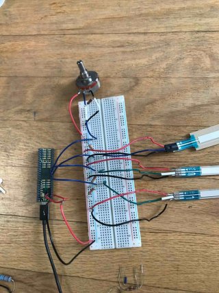
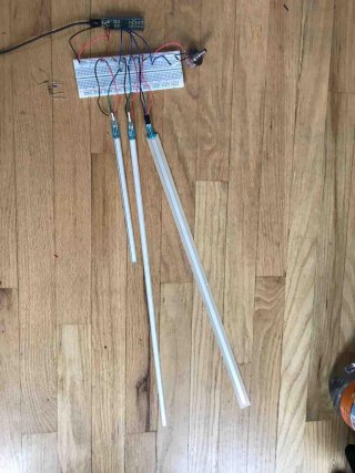
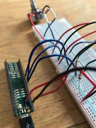
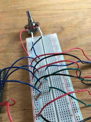
Ok here are some images.

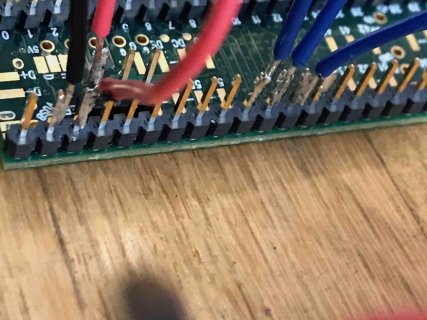
It might be hard to see what's going on so I'll explain it as well. Aref is connected to 3.3V. Coming out of each sensor is a power, ground and signal. Except for the regular Potentiometer, each sensor's signal is going to a 22k resistor that is connected to ground. The sensor signals are also connected to A0 A1 A2 A3.

Let me know if I'm missing something.

bb1.jpg
bb3.jpg
bb4.jpg
bb5.jpg
bb6.jpg
bb7.jpg
 
I believe AREF is only used with external references and needs to be set in code somehow... but I don't think it's a problem if it's getting supplied the internal voltage but it's not doing anything.

Is that connection why the Teensy is not in the breadboard?

Maybe smaller resistors would pull to ground harder and eliminate the problem. If it made it worse then I'd figure it was a grounding problem somehow.

I can't see where the higher voltage is getting to the other pins.
 
I tried it without aref and it was way more unstable, so aref helps a lot. I just figured I should use it since I've used it previously in my Arduino projects.

Maybe I should add this line to my code

Code:
 analogReference(EXTERNAL);

I don't have many varieties of resistors around. I tried 330 Ohms, which is probably way to small, and most of the sensors read 127 when they should be at 0.

I'll order a bunch of resistors of different values less than 10k ohms and let you know how that works out. It might take a while to get these.

I guess what I am puzzled about is that I wired my arduino mega exactly like how this is wired, with 10k ohms resistors, and it worked fine. I wonder why this is different. If anyone has any ideas please let me know.

You can use external reference voltage but by this other sensors also be affected by reducing their ranges. I not recommend this method, even using resistors because they have strong affects too, linearity mess. You can use resistor just in case but 1Mohm minimum, rest need be done by coding. You can also try other options with connection. You can use digital pins for supplying softpot and analog for reading. Reading current changes between pins and wiper and so on. Best option is trying get solutions by coding. I had too many problems with my SoftPot but all I overcome by coding. Some tricks with smoothing, last value/current values and so on. Useful is constrain function. Some examples:

sensorForceValue =
map(sensorForceRawValue, sensorForceMinValue,
sensorForceMaxValue, 0, 127); // apply the
calibration to force sensor reading
sensorForceValue =
constrain(sensorForceValue, 0, 127);

Or:

if (sensorPositionRawValue>
(sensorPositionMinValue)){
if
((sensorPositionRawValue<(sensorPositionPreviousVal
ue-securityRange))||(sensorPositionRawValue>
(sensorPositionPreviousValue+securityRange))){
//ignores little variations
sensorPositionPreviousValue =
sensorPositionRawValue; //records input value to
check little variations at next do
sensorPositionValue =
map(sensorPositionRawValue, sensorPositionMinValue,
sensorPositionMaxValue,minNote, maxNote);// apply
the calibration to the position sensor reading
sensorPositionValue =
constrain(sensorPositionValue, minNote, maxNote);//
in case the position sensor value is outside the
range seen during calibration
if (sensorPositionValue!=lastNote){
//if changed
MIDI.sendNoteOff(lastNote,0,midiChannel); // Stop
the note
MIDI.sendNoteOn(sensorPositionValue,100,midiChannel
); // Send a Note (pitch 42, velo 127 on channel
1)
lastNote=sensorPositionValue; //
register the played note in order to stop it later
} }
if((sensorForceValue!=sensorForcePreviousValue)&&
(sensorForceRawValue>
(sensorForceMinValue+securityRange))){
sensorForcePreviousValue=sensorForceValue;
MIDI.sendControlChange(ccForce,
sensorForceValue, midiChannel);// send midi control
change defined by force sensor
} }
}while(sensorPositionLastValue>
(sensorPositionMinValue+10)); //loops till the
sensor is pressed
MIDI.sendNoteOff(lastNote,0,midiChannel);


Good luck!
 
Hi Kirazvora,

I learned from someone else on this forum that it's good to put a small capacitor between the power and ground. As a matter of fact, for midi controllers, if you have a potentiometer and don't have a cap you get way too much midi information and it was overloading my computer and causing the software to crash. Adding a cap made it so it was stablized and only sends a value if I move the Pot.

I need to do more breadboard experimenting with code, resistors, and caps. But in all my tests you need to have a resistor, but it has to be the right value so that you will get a linear reading (if that's what you want) and a cap for stability. The aref seems to help for me. In terms of code, I have it so that it only sends a value if the sensor changes so you don't get flooded with unnecessary data.

Here's some videos of the finished product with the soft pots, regular pots, LEDs etc:

https://www.youtube.com/watch?v=Qf6HLF9j39o

https://www.youtube.com/watch?v=b-AcxC85yLs

thanks, Nick

That’s true capacitors 10n even 100n definitely help with potentiometers dropping problems. In my first rev my ribbon I used caps and resistor but like I said, they changed linearity and always pulling down last value to the threshold made by resistor. It was not elegant and ribbon was not really playable. Even after really settled values cap and resistor still it was far away from what I wanted to get. I spend lots of time for testing different options with connection ribbon and I got interesting results with current reading , combination digital outputs for powering ribbon and ADC for wiper without any caps, just I use 2Mohm between wiper and gnd, it is not necessary because working without resistor. But just in case :) and of course piece of coding. I used couple of functions for smoothing, reading, mapping counting values really lot of code lines :) But I got nice linearity, no dropping values, no mess with flooding data, ribbon keeping last position and if I use mode with independent sensor for trigger/velocity I can play last position even without keeping fingers on strip , even if not triggered but I touch ribbon for new position , then position is applied and playing without finger on ribbon when trigger I use again! Very playable and positions are available always in the same spot. Not changing their spots if I touch ribbon. I spent last 4 week almost 10h per day for getting my code to max what I can do. Still is not finished because I not implementing all wanted options for my controller but I can play and some functions is done. Very soon I put here some important parts of my code. Maybe will be useful for you and others:)
 
Kirazvora, wow that sounds amazing. Please post some video or images. I'd love to see what you do with this.

Thanks, Nick
 
Status
Not open for further replies.
Back
Top