controlling the amplitude of a PWM

Status
Not open for further replies.

paul_H

Member
Hello every body

I am trying to get a PWM that sweep from a min to max value, with controllable frequency.
I really get the signal as I expected!
but now I am wondering how can change the amplitude of the signal in my code:

Code:
int minimum_pwm_value=10;
int maximum_pwm_value=150;
// to determine the range of PWM to sweep
void setup() {
  // put your setup code here, to run once:
  pinMode(9, OUTPUT);//PWM PIN
  analogWriteResolution(8); // can be 2-16 bit
  Serial.begin(9600);
  delay(2);
}

void loop() {
  // put your main code here, to run repeatedly:
analogWriteFrequency(9, 100); // FREQ IN Hz
  for (int i=minimum_pwm_value;i<=maximum_pwm_value;i++)
 { analogWrite(9,i);//0-255 / pwm value / 8bits
 delay(10);
 
  }
 
}

I am waiting for your help :D
 
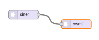
It's said a picture is worth 1000 words. So, like this:

sc.png

For the 1000 words, please read the audio library tutorial. Or if you'd prefer to watch instead of read a 31 page PDF, scroll down on that page to the video where Alysia and I demonstrate the entire tutorial in ~45 minutes.

The main idea is to read or watch part 2 where the design tool is explained, and to generally understand how the library let you connect audio objects together. It can do so much more than just a sine wave to a PWM output, but that's what you said you wanted...
 
It can do so much more than just a sine wave to a PWM output, but that's what you said you wanted...

mmm in my post, I said that I want a PWM signal with controllable freq, amplitude and PWM value. not a sine wave! my first post may was not clear

In my simple code I can change freq and pwm value put not amplitude.
simply, I just would like to know how can I change it.
 
You could also do something like this.

sc.png

The normal PWM pins always use logic low (zero voltage) and logic high (3.3V). Only the DAC pins are capable of creating analog voltages different than logic low and logic high.
 
just decided to give up stm32arduino from all the bugs on stm32f4 and decided to move teensy 3.6 , my project requires having to generate 4 pwms each with different frequency and Duty cycle also connect 4 rotary encoders , with 4 analog using 13 bit adc the frequencies will vary from 1 to 400 Hz , can you show me a sample how to do the 4 PWM working without conflicts as i can see the example with 4 encoder working.
 
just decided to give up stm32arduino from all the bugs on stm32f4 and decided to move teensy 3.6 , my project requires having to generate 4 pwms each with different frequency and Duty cycle also connect 4 rotary encoders , with 4 analog using 13 bit adc the frequencies will vary from 1 to 400 Hz , can you show me a sample how to do the 4 PWM working without conflicts as i can see the example with 4 encoder working.
Study the K66 processor reference manual and identify 4 pins of your choice which can be multiplexed to one of the 4 different Flextimers each. Use these for 4 independent PWM signals.
 
thank you , just tried a sample code on teensy 3.2 and worked fine with 3 pwm with different frequency, esp32 can do more PWMs with the same way.
 
Status
Not open for further replies.
Back
Top