Overuse of pin 10 (CS and Serial2)

Status
Not open for further replies.

mariusj

Member
Hi,
I'm using a Teensy 3.2 Board and i would like to use the ethernet module WIZ820io. Its works with the Ethernet-Library. ChipSelect: Pin 10.
Additionally i was to use 3 RS232 (Serial) ports, including Serial2 whose TX2 is at pin 10 too.

Do you guys have any ideas how to solve this?

Looking at the pinout i noticed a few other pins where CS is written in gray but i could not figure out how to change the default chip select pin.
I tried Ethernet.init(15) in the setup routine but it didnt work. How to change the default chip select pin of the ethernet library?

Another way would be to move Serial2 to other pins which could be made by software tricks. Maybe you can tell me how that works if there is no other way.

Thanks for any advice!
 
I tried Ethernet.init(15) in the setup routine but it didnt work. How to change the default chip select pin of the ethernet library?

That's how you're supposed to do it.

Maybe you did things in the wrong order, like init() after begin()? Generally we ask that you post the complete program (eg, the "Forum Rule") because it lets us much better help you with subtle issues like this.


Another way would be to move Serial2 to other pins which could be made by software tricks. Maybe you can tell me how that works if there is no other way.

Serial2.setTX(pin)

Details here:

https://www.pjrc.com/teensy/td_uart.html
 
I tested this using the WebServer program from Examples.
Here is my code:
Code:
/*
  Web Server

 A simple web server that shows the value of the analog input pins.
 using an Arduino Wiznet Ethernet shield.

 Circuit:
 * Ethernet shield attached to pins 10, 11, 12, 13
 * Analog inputs attached to pins A0 through A5 (optional)

 created 18 Dec 2009
 by David A. Mellis
 modified 9 Apr 2012
 by Tom Igoe
 modified 02 Sept 2015
 by Arturo Guadalupi
 
 */

#include <SPI.h>
#include <Ethernet.h>
// Enter a MAC address and IP address for your controller below.
// The IP address will be dependent on your local network:
byte mac[] = {
  0xDE, 0xAD, 0xBE, 0xEF, 0xFE, 0xED
};
IPAddress ip(192, 168, 1, 177);

// Initialize the Ethernet server library
// with the IP address and port you want to use
// (port 80 is default for HTTP):
EthernetServer server(80);

void setup() {
Ethernet.init(15);
  // Open serial communications and wait for port to open:
  Serial.begin(9600);
  while (!Serial) {
    ; // wait for serial port to connect. Needed for native USB port only
  }


  // start the Ethernet connection and the server:
  Ethernet.begin(mac, ip);
  server.begin();
  Serial.print("server is at ");
  Serial.println(Ethernet.localIP());
  int r = PIN_SPI_SS;
  Serial.println(r);
}


void loop() {
  // listen for incoming clients
  EthernetClient client = server.available();
  if (client) {
    Serial.println("new client");
    // an http request ends with a blank line
    boolean currentLineIsBlank = true;
    while (client.connected()) {
      if (client.available()) {
        char c = client.read();
        Serial.write(c);
        // if you've gotten to the end of the line (received a newline
        // character) and the line is blank, the http request has ended,
        // so you can send a reply
        if (c == '\n' && currentLineIsBlank) {
          // send a standard http response header
          client.println("HTTP/1.1 200 OK");
          client.println("Content-Type: text/html");
          client.println("Connection: close");  // the connection will be closed after completion of the response
          client.println("Refresh: 5");  // refresh the page automatically every 5 sec
          client.println();
          client.println("<!DOCTYPE HTML>");
          client.println("<html>");
          // output the value of each analog input pin
          for (int analogChannel = 0; analogChannel < 6; analogChannel++) {
            int sensorReading = analogRead(analogChannel);
            client.print("analog input ");
            client.print(analogChannel);
            client.print(" is ");
            client.print(sensorReading);
            client.println("<br />");
          }
          client.println("</html>");
          break;
        }
        if (c == '\n') {
          // you're starting a new line
          currentLineIsBlank = true;
        } else if (c != '\r') {
          // you've gotten a character on the current line
          currentLineIsBlank = false;
        }
      }
    }
    // give the web browser time to receive the data
    delay(1);
    // close the connection:
    client.stop();
    Serial.println("client disconnected");
  }
}

I printed the PIN_SPI_SS constant from the W5100.cpp which is used by the ethernet library and seems zu contain the pin nr.
I connected the ethernet modul correctly (CS pin 10), programmed it without the Ethernet.init line and it printed:
"server is at 192.168.1.177
10"
So the server started correctly and the CS constant in the library is 10.
Now i soldered the CS pin to pin 15 and tried the code which is shown above.
Output:
"server is at 0.0.0.0
10"
So it didnt start correctly and the constant in the library is still 10.

Oh, and I used Teensyduino 1.37
 
Last edited:
So it didnt start correctly and the constant in the library is still 10.

the Ethernet.init(15) will not change the value of PIN_SPI_SS, it will cause the library to use pin 15 as CS for SPI. So your print is not a meaningful test. do you have an analyzer or scope to look at SPI activity?
 
Okay... That's weird. The ethernet module seems not to answer on MISO.
bild1.jpg
bild2.png
 
Right now it doesn't even work on the first way (pin 10 CS). I will figure it out in the next few days.
Thanks for your support so far. In the worst case I will try to select a different TX2 pin.
 
I tested just now with this code:

Code:
#include <SPI.h>
#include <Ethernet.h>
// Enter a MAC address and IP address for your controller below.
// The IP address will be dependent on your local network:
byte mac[] = {
  0xDE, 0xAD, 0xBE, 0xEF, 0xFE, 0xED
};
IPAddress ip(192, 168, 1, 177);

// Initialize the Ethernet server library
// with the IP address and port you want to use
// (port 80 is default for HTTP):
EthernetServer server(80);

void setup() {
  Ethernet.init(15);
  // Open serial communications and wait for port to open:
  Serial.begin(9600);
  while (!Serial) {
    ; // wait for serial port to connect. Needed for native USB port only
  }

  // start the Ethernet connection and the server:
  Ethernet.begin(mac, ip);
  server.begin();
  Serial.print("server is at ");
  Serial.println(Ethernet.localIP());
  int r = PIN_SPI_SS;
  Serial.println(r);
}

void loop() {

}

It prints this in the serial monitor:

Code:
server is at 192.168.1.177
10

I also ran the WebClient example, with "Ethernet.init(15);" added at the beginning of setup(). It successfully fetched the web page from google's server.

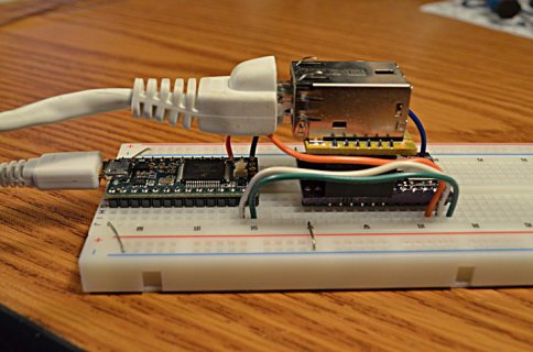
Here's the hardware on my bench right now, which I used for this test. The orange wire is the CS signal, connected to pin 15.

DSC_0968_web.jpg
(click for full size)


Any chance the problems you're seeing are simply a wiring mistake? CS on pin 15 definitely does work.
 
It is sometimes hard to see for sure what your signals are doing in the Logic Analyzer. Maybe did not run the software to capture at a high enough speed.

Also as Paul mentioned, you should double check wiring. Also maybe post a picture. Pictures help to see subtle issues. Like if you are using a breadboard, are the pins actually soldered to the Teensy? That is one of the common problems we have seen. Or maybe a ground wire was not run, or maybe the wires are not making good contact.
 
Thank you so much for help!
I can't believe you even build it up :D

My mistake was the nReset pin. I used to connect it to an I/O Pin to reset the ethernet module in the setup routine, which doesn't happen in my program so the modules reset status was undefined.

It works!
 
Status
Not open for further replies.
Back
Top