use SPI.h for 3 wire SPI

Status
Not open for further replies.
Hello,

I am unclear on how to use a device which has only CS, SCL, and MOSI/MISO (MOSI/MISO are one line tied together.)

The module is the MMA7455l from parallax: https://www.parallax.com/product/28526

As far as I can tell, my Teensy 3.2 can only communicate using one pin for MOSI and another for MISO. Is there a way to use just one, or to put two resistors between the two so that the can both interface to this one pin?

i.e.:
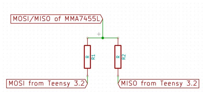
teensyspischematic.jpg

Thanks much
 
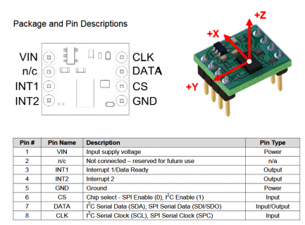
From my reading of the data sheet (Table 8), it looks like in SPI mode Pin 12 is Serial Data Out (aka MISO), Pin13 is Serial Data In (aka MOSI), Pin 7 is CS (aka SS), and Pin 14 is SPI Clock. The data lines aren’t bidirectional.
 
As I said, from my reading of the datasheet (Page 19, Table 8) , the MMA7455 is NOT a one-line device in SPI mode. So, I think your question is moot.
 
Do you think the two lines could be tied in a way so as to not interfere with one another and yet still communicate with the one line device?

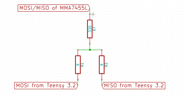
Maybe, but it's a little risky if you ever leave MOSI enabled & driving the line while the other chip also drives the data line. During testing, I'd suggest adding a 330 ohm resistor between Teensy and whatever other device you use. If both drive the line at the same moment, at least they'll be driving the 2 sides of a resistor.

To try this, perhaps you could write to the pin config register for pin 11. First, read the register and store the value (which the SPI library wrote) into a 32 bit variable. When you want to turn off MOSI, writing a zero to that register, which puts pin 11 into a low power shutdown state. When you want to turn MOSI back on, just restore that value to the port config register.
 
As I said, from my reading of the datasheet (Page 19, Table 8) , the MMA7455 is NOT a one-line device in SPI mode. So, I think your question is moot.

However, the package that is a breakout of this device does not provide the MISO line.
 
gfvalvo
- Also, to rephrase the question if it wasn't clear. I am trying to use a device that must be used in 3 wire SPI mode because of the package from Parallax. Therefore I need to use MOSI and MISO together.
 
Maybe, but it's a little risky if you ever leave MOSI enabled & driving the line while the other chip also drives the data line. During testing, I'd suggest adding a 330 ohm resistor between Teensy and whatever other device you use. If both drive the line at the same moment, at least they'll be driving the 2 sides of a resistor.

To try this, perhaps you could write to the pin config register for pin 11. First, read the register and store the value (which the SPI library wrote) into a 32 bit variable. When you want to turn off MOSI, writing a zero to that register, which puts pin 11 into a low power shutdown state. When you want to turn MOSI back on, just restore that value to the port config register.

Paul, I assume you mean something like this ?

teensyspischematic.png

Here is a pic of the device schemtic

teensyspiMMA7455schematic.png
 
i am not sure how that could work...

That is with SPI, as each clock happens, data from the host is shifted out on MOSI and data from the slave is shifted in on MISO... Even in logical read operations, you typically send out a byte of 0s...

Now maybe you could really hack things up and if you know that the data is only going one direction, either out from host or in from client.
When going out, you have the MOSI pin setup as a normal SPI mode and when you know data is only coming back, you switch the MOSI pin to a standard IO pin in INPUT mode, so it is sort of floating and allows the slave to then drive it...

I don't think that's possible with the SPI.h library, as the write and read operation take place at the same time. I'd prefer not to bit-bang it if possible - I suppose I could if I had too- but it is for a auto-leveling quadcopter that flies well but needs an accelerator to maintain angle without drift. Therefore it needs to run extremely fast.
 
I don't think that's possible with the SPI.h library, as the write and read operation take place at the same time. I'd prefer not to bit-bang it if possible - I suppose I could if I had too- but it is for a auto-leveling quadcopter that flies well but needs an accelerator to maintain angle without drift. Therefore it needs to run extremely fast.

Again if the device only has the 3 wires for SPI (CS, MOSI/MISO, SCK), it must have some internal protocol where it is only using MOSI or MISO, but not both on the same byte transfer... So IF you know how each byte is being used, then you can do the tricks I mentioned... As far as SPI would be concerned it output the data to MOSI, but MOSI would not be connected to a pin so...

I noticed that their Arduino example code uses I2C. So probably the best approach. As for fasted speed, not sure... Depends on what options you use to compile T3.2... 96mhz CPU? so F_BUS would probably be 48mhz... You can optionally try setting F_BUS to 96mhz in kinetis.h... If this is true I think the I2C can run at 1mhz... Of course not sure if your chip can run that fast or not...

Excellent. I will give I2C a go, otherwise I will attempt to implement your SPI suggestions. Thanks much!
 
Status
Not open for further replies.
Back
Top