numero uno
Member
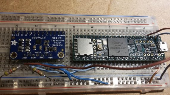
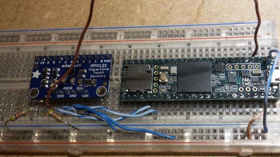
I've downloaded an arduino compatible library for the MPR121 sensor. This sensor comunicates using i2c protocol. Here are pictures of my wiring:


I have modified the code a bit compared to the original code where I downloaded this from. I changed the i2c pins to the pins 37 and 38, and I added a "Serial.println("hello world");" in the setup function.
The problem I am having is that nothing is being printed in the console, not even the hello world i printed in the setup function. here is the arduino code:
and here is the contents of MPR121.h:
Any ideas of what I can try next would be apreciated.


I have modified the code a bit compared to the original code where I downloaded this from. I changed the i2c pins to the pins 37 and 38, and I added a "Serial.println("hello world");" in the setup function.
The problem I am having is that nothing is being printed in the console, not even the hello world i printed in the setup function. here is the arduino code:
Code:
#include "mpr121.h"
#include <Wire.h>

int irqpin = 2;  // Digital 2
int SDApin = 38;
int SCLpin = 37;
boolean touchStates[12]; //to keep track of the previous touch states

void setup(){
  pinMode(irqpin, INPUT);
  digitalWrite(irqpin, HIGH); //enable pullup resistor

  Serial.begin(9600);
  Serial.println("hello world");
  Wire.setSDA(SDApin);
  Wire.setSCL(SCLpin);
  Wire.begin();

  mpr121_setup();
}

void loop(){
  readTouchInputs();
}


void readTouchInputs(){
  if(!checkInterrupt()){

    //read the touch state from the MPR121
    Wire.requestFrom(0x5A,2);

    byte LSB = Wire.read();
    byte MSB = Wire.read();

    uint16_t touched = ((MSB << 8) | LSB); //16bits that make up the touch states


    for (int i=0; i < 12; i++){  // Check what electrodes were pressed
      if(touched & (1<<i)){

        if(touchStates[i] == 0){
          //pin i was just touched
          Serial.print("pin ");
          Serial.print(i);
          Serial.println(" was just touched");

        }else if(touchStates[i] == 1){
          //pin i is still being touched
        }

        touchStates[i] = 1;
      }else{
        if(touchStates[i] == 1){
          Serial.print("pin ");
          Serial.print(i);
          Serial.println(" is no longer being touched");

          //pin i is no longer being touched
       }

        touchStates[i] = 0;
      }

    }

  }
}


void mpr121_setup(void){

  set_register(0x5A, ELE_CFG, 0x00);

  // Section A - Controls filtering when data is > baseline.
  set_register(0x5A, MHD_R, 0x01);
  set_register(0x5A, NHD_R, 0x01);
  set_register(0x5A, NCL_R, 0x00);
  set_register(0x5A, FDL_R, 0x00);

  // Section B - Controls filtering when data is < baseline.
  set_register(0x5A, MHD_F, 0x01);
  set_register(0x5A, NHD_F, 0x01);
  set_register(0x5A, NCL_F, 0xFF);
  set_register(0x5A, FDL_F, 0x02);

  // Section C - Sets touch and release thresholds for each electrode
  set_register(0x5A, ELE0_T, TOU_THRESH);
  set_register(0x5A, ELE0_R, REL_THRESH);

  set_register(0x5A, ELE1_T, TOU_THRESH);
  set_register(0x5A, ELE1_R, REL_THRESH);

  set_register(0x5A, ELE2_T, TOU_THRESH);
  set_register(0x5A, ELE2_R, REL_THRESH);

  set_register(0x5A, ELE3_T, TOU_THRESH);
  set_register(0x5A, ELE3_R, REL_THRESH);

  set_register(0x5A, ELE4_T, TOU_THRESH);
  set_register(0x5A, ELE4_R, REL_THRESH);

  set_register(0x5A, ELE5_T, TOU_THRESH);
  set_register(0x5A, ELE5_R, REL_THRESH);

  set_register(0x5A, ELE6_T, TOU_THRESH);
  set_register(0x5A, ELE6_R, REL_THRESH);

  set_register(0x5A, ELE7_T, TOU_THRESH);
  set_register(0x5A, ELE7_R, REL_THRESH);

  set_register(0x5A, ELE8_T, TOU_THRESH);
  set_register(0x5A, ELE8_R, REL_THRESH);

  set_register(0x5A, ELE9_T, TOU_THRESH);
  set_register(0x5A, ELE9_R, REL_THRESH);

  set_register(0x5A, ELE10_T, TOU_THRESH);
  set_register(0x5A, ELE10_R, REL_THRESH);

  set_register(0x5A, ELE11_T, TOU_THRESH);
  set_register(0x5A, ELE11_R, REL_THRESH);

  // Section D
  // Set the Filter Configuration
  // Set ESI2
  set_register(0x5A, FIL_CFG, 0x04);

  // Section E
  // Electrode Configuration
  // Set ELE_CFG to 0x00 to return to standby mode
  set_register(0x5A, ELE_CFG, 0x0C);  // Enables all 12 Electrodes


  // Section F
  // Enable Auto Config and auto Reconfig
  /*set_register(0x5A, ATO_CFG0, 0x0B);
  set_register(0x5A, ATO_CFGU, 0xC9);  // USL = (Vdd-0.7)/vdd*256 = 0xC9 @3.3V   set_register(0x5A, ATO_CFGL, 0x82);  // LSL = 0.65*USL = 0x82 @3.3V
  set_register(0x5A, ATO_CFGT, 0xB5);*/  // Target = 0.9*USL = 0xB5 @3.3V

  set_register(0x5A, ELE_CFG, 0x0C);

}


boolean checkInterrupt(void){
  return digitalRead(irqpin);
}


void set_register(int address, unsigned char r, unsigned char v){
    Wire.beginTransmission(address);
    Wire.write(r);
    Wire.write(v);
    Wire.endTransmission();
}
Code:
// MPR121 Register Defines
#define MHD_R	0x2B
#define NHD_R	0x2C
#define	NCL_R 	0x2D
#define	FDL_R	0x2E
#define	MHD_F	0x2F
#define	NHD_F	0x30
#define	NCL_F	0x31
#define	FDL_F	0x32
#define	ELE0_T	0x41
#define	ELE0_R	0x42
#define	ELE1_T	0x43
#define	ELE1_R	0x44
#define	ELE2_T	0x45
#define	ELE2_R	0x46
#define	ELE3_T	0x47
#define	ELE3_R	0x48
#define	ELE4_T	0x49
#define	ELE4_R	0x4A
#define	ELE5_T	0x4B
#define	ELE5_R	0x4C
#define	ELE6_T	0x4D
#define	ELE6_R	0x4E
#define	ELE7_T	0x4F
#define	ELE7_R	0x50
#define	ELE8_T	0x51
#define	ELE8_R	0x52
#define	ELE9_T	0x53
#define	ELE9_R	0x54
#define	ELE10_T	0x55
#define	ELE10_R	0x56
#define	ELE11_T	0x57
#define	ELE11_R	0x58
#define	FIL_CFG	0x5D
#define	ELE_CFG	0x5E
#define GPIO_CTRL0	0x73
#define	GPIO_CTRL1	0x74
#define GPIO_DATA	0x75
#define	GPIO_DIR	0x76
#define	GPIO_EN		0x77
#define	GPIO_SET	0x78
#define	GPIO_CLEAR	0x79
#define	GPIO_TOGGLE	0x7A
#define	ATO_CFG0	0x7B
#define	ATO_CFGU	0x7D
#define	ATO_CFGL	0x7E
#define	ATO_CFGT	0x7F


// Global Constants
#define TOU_THRESH	0x06
#define	REL_THRESH	0x0A
Any ideas of what I can try next would be apreciated.

