OctoWS2811 LED Library with Realtime video source?

Status
Not open for further replies.
Hello-

I've just found the OctoWS2811 LED Library source, and I am very impressed. I am beginning a project that requires a grid 1650 LEDs. I will be using strings of WS2811 12mm LEDs (not strips). I have previously done a project using FastLED library with LED strips, but the video content was generated in realtime on a computer, and driven by the "adalight" processing sketch:

https://learn.adafruit.com/adalight-diy-ambient-tv-lighting/download-and-install

This processing sketch samples the computers video screen in realtime and uses that to drive the LEDs. My current project requires many interactive elements with dynamic video that is being generated in realtime. Is there a simple way to use the OctoWS2811 LED Library, but change the processing sketch source from a movie to a realtime screen sampling? Any advice is appreciated. Thanks very much!
 
Is there a simple way to use the OctoWS2811 LED Library, but change the processing sketch source from a movie to a realtime screen sampling?

This question really revolves around the meaning of the word "simple". ;)

Years ago I did pretty much exactly this in a not-so-simple way, all written in C code. I copied some X11 sample code (so pretty much a Linux only approach) to scrape pixels from the screen buffer. It was horribly inefficient (like running 50% CPU time on a laptop) but worked.

The project also involved a music visualizer program which I didn't write, but there's a "run.sh" shell script which causes it to run in a very tiny 60x32 pixel window which matches the size of the LED array used. The C code that screen scrapes the pixels looks for the window with the name that program uses, so it can automatically find the right screen coordinates regardless of where that little 60x32 window is on the screen. Well, as long as you don't move it, since it only finds the window at startup, the 30 times a second just scrapes whatever 60x32 pixels are at that location and transmits them to two Teensy board running OctoWS2811 VideoDisplay.

This was just a quick hack project, never actually documented in any way. But here's all the source code. :)
 

Attachments

  • ledvisual_02.zip
    48.3 KB · Views: 129
Hi joshupenrose, I'm doing something very similar to what you're describing for this project.

I'm working with Processing and scanned the portion of the screen I want the LEDs to show and saved it to an array. That part is relatively easy, but I have now to start looking for a way to adapt movie2data for this sketch.

Maybe we can work it side by side here.
 
This was just a quick hack project, never actually documented in any way. But here's all the source code. :)

Hi Paul,

Thanks for the response and the example code. In the past, I had been using the adalight processing sketch as a kludge, my video content is being generated in Max7 (jitter). After having looked through the VideoDisplay example arduino code and the movie2serial Processing code, I think I may have a shot at building a platform in Max to talk to the arduino side of your code over serial. Do you know off the top of your head if this already exists somewhere? I have some experience in formatting serial communications in Max to talk with arduino. It seems the trick is how to get the data formatted the way the your arduino code wants to receive it.

I get the "Start-Of-Message" character portion, but maybe you can help me understanding the next steps? In Max I can easily parse the ARGB data of each pixel, but I think I'll need to convert RGB to hexadecimal, right? And then in the image2data section of the movie2serial processing sketch, something happens with chunks of 8 pixels that I'm not quite following. Any chance you can help me better understand that process? And then finally, once an entire image has been transmitted, is there any line ending or carriage return character, or is the arduino code simply waiting for the next "Start-Of-Message" character again?

@maurobarreca: thanks for the invite, but as I've said, developing a real-time tool in processing would just be a better kludge for me, I'm hoping to dive into this build in Max. But good luck to you!

Many thanks!
Joshua
 
Hello all-

I'm attempting to understand the data format coming out of the "movie2serial" processing sketch in order to understand how to format the data I want to send out of my Max patch.

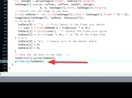
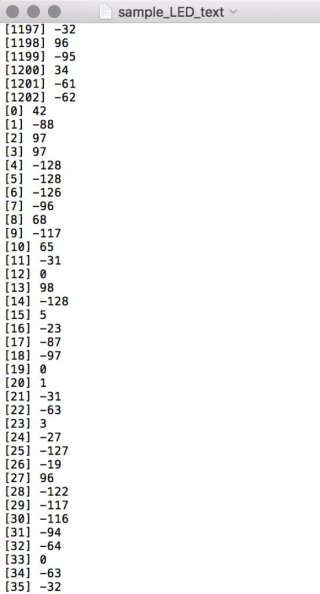
By adding a printArray line in the Movie2Serial processing sketch, I'm able to see the contents of the array that processing is pushing out to the Teensy. I see that the first character of each group is "42", which is the ASCII character for an "*", which I would expect as the character telling the Teensy it is in charge of the frame sync pulse (master).

What has me confused, however, is that if these are all ASCII characters, then I have a ton of what look like negative integers, which I cannot account for. I wouldn't expect to see negative integers is the data is straight ASCII. This makes me think there's something else going on here.

Also worth mentioning, I have the Teensy programmed for an LED_HEIGHT of 16, and LED_WIDTH of 25. So It's running 400 LEDs, and my array size is 1203. So minus the 3 header values, that leaves me with 3 values per LED. Also, I've notice my lowest value is -128 and my highest value (at least in this sample) is 124. Could these simply be my RGB values of 0-255 but offset by -128 for some reason?

Can anyone explain the negative integers in the raw data being sent to the Teensy? Or how I should be looking at this data? Any help is appreciated!


printarray.png

ledData_sample.jpg
 
It shows it that way because ledData is a byte type array. Bytes can only be whole numbers between -128 and 127.

For what I understood, the structure of the array is:

[0] // '*', '$', '%', '@', '?' (to send display data to one Teensy use '*')
[1] // 75% of the duration of a frame in microseconds
[2] // splitted into two bytes ([1] and [2]) in binary
[3-x] // RGB data (or GRB, you have to know the order used by the LED wiring). The order of the pixels is as if drawing the 8 outputs at the same time: first the first RGB values for the first pixel of the first 8 outputs, then the second pixel of the 8 outputs, and so on. What image2data does here is reordering the pixels (to match what I described) and convert the values of the pixels of the 8 outputs to 24 bytes (raw data for the Teensy and WS2811 series).
 
Status
Not open for further replies.
Back
Top