SPI library on Teency 3.2

Status
Not open for further replies.
(shakes head) I don't think anyone here is going to write the code for you. We will provide tips & hints. The .cpp is the <CODE> you need to program the Teensy in the Arduino environment There are also some header .h (driver) files that you include in your code. I realize the link to my post on the FTM as encoder was not explicit, but there was code you could use to explore how it works as a quadrature encoder. I provided a few hints in that post too. We are all hackers here who take what others have done before us and shape it into what we need. No body here would give you Perl code to run on a Teensy. I also note you are using a T3.1 which may have yet another manual to peruse to determine how the FTM functions on a T3.1. Paul has done an excellent job in keeping the nomenclature used in the manual to be part of the commands to make it easier for all of us to use Teensy.

I am so sorry grease_lighting, I am pretty new to Arduino and Teency and it is not easy for me to understand the FTM code.
 
Lorenzo,
Let's try isolate if the problem is with the encoders or with the LS7366R communication.
Hook up the Teensy as listed in the file header comments then try to run this program.
Power the LS7366R board from 5 Volts. (The data sheet says that it has a 40mhz crystal on the board, and that's only reliable at 5V.)
This program writes numbers to the 32-bit CNTR register in the LS7366R, then reads them back. No encoder is needed.
This will tell you if you are communicating with the LS7366R Quadrature Decoder Chip.
Code:
/*
* LS7366R COMMUNICATION TEST
* 
*  LS7366R      Teensy
*  4 SS         10  SS
*  5 SCK        14  ALT SCK
*  6 MISO       11  MOSI
*  7 MOSI       12  MISO
                13  Builtin LED
*/

#include <SPI.h>

#define CLR B00000000
#define RD B01000000
#define WR B10000000
#define LOAD B11000000

#define MDR0 B00001000
#define MDR1 B00010000
#define DTR B00011000
#define CNTR B00100000
#define OTR B00101000
#define STR B00110000

#define SS  10   // Slave Select Pin
#define LED  13  // Teensy 3 Builtin LED

// filter factor 1
// async index
// no index
// free-running
// 4x quadrature
#define MDR0_CONF B00000011

// no flag
// enabled
// 32 bits
#define MDR1_CONF B00000000

SPISettings settings(16000000, MSBFIRST, SPI_MODE1); 

void setup() {
  Serial.begin(9600);
  pinMode(LED, OUTPUT);
  pinMode(SS, OUTPUT);
  SPI.setSCK(14);      //redefine SCK from Pin 13 to Pin 14 for Teensy3.2
  //SPI.setMOSI(7);    //alternate Teensy 3X MOSI pin,  pin 11 is default
  //SPI.setMISO(8);    //alternate Teensy 3X MISO pin,  pin 12 is default
  SPI.begin();
  pinMode(SS, OUTPUT);
  
  SPI.beginTransaction(settings);
  digitalWrite(SS, LOW);
  SPI.transfer(WR | MDR0);
  SPI.transfer(MDR0_CONF);
  digitalWrite(SS, HIGH);
  
  digitalWrite(SS, LOW);
  SPI.transfer(WR | MDR1);
  SPI.transfer(MDR1_CONF);
  digitalWrite(SS, HIGH);
  
  digitalWrite(SS, LOW);
  SPI.transfer(CLR | CNTR);
  digitalWrite(SS, HIGH);
  SPI.endTransaction();
}

long count = 0;

void loop() {
  
  for (byte COUNTER = B00000000; COUNTER <= B11111111; COUNTER++){

  // Write Numbers to DTR then parallel shift to CNTR  
  SPI.beginTransaction(settings);
  digitalWrite(SS, LOW);
  SPI.transfer(WR|DTR);
  SPI.transfer(COUNTER);
  SPI.transfer(COUNTER);
  SPI.transfer(COUNTER);
  SPI.transfer(COUNTER);
  digitalWrite(SS, HIGH);
  delayMicroseconds(10);
  digitalWrite(SS, LOW);
  SPI.transfer(LOAD|CNTR);
  digitalWrite(SS, HIGH);
  delayMicroseconds(10);
  digitalWrite(SS, LOW);

  // Read Numbers from CNTR
  SPI.transfer((byte) RD | CNTR);
  count = SPI.transfer(0x00);
  count <<= 8;
  count |= SPI.transfer(0x00);
  count <<= 8;
  count |= SPI.transfer(0x00);
  count <<= 8;
  count |= SPI.transfer(0x00);
  digitalWrite(SS, HIGH);
  SPI.endTransaction();
  Serial.print(count);
  Serial.println();
  digitalWrite(13,!digitalRead(13));
  delayMicroseconds(50000);
  }
}

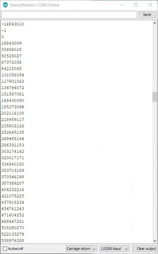
The serial output in the Arduino serial monitor should look something like this:
2018-02-02 19_20_36-TeensyMonitor_ COM3 Online.jpg
 
Lorenzo,
Let's try isolate if the problem is with the encoders or with the LS7366R communication.
Hook up the Teensy as listed in the file header comments then try to run this program.
Power the LS7366R board from 5 Volts. (The data sheet says that it has a 40mhz crystal on the board, and that's only reliable at 5V.)
This program writes numbers to the 32-bit CNTR register in the LS7366R, then reads them back. No encoder is needed.
This will tell you if you are communicating with the LS7366R Quadrature Decoder Chip.
Code:
/*
* LS7366R COMMUNICATION TEST
* 
*  LS7366R      Teensy
*  4 SS         10  SS
*  5 SCK        14  ALT SCK
*  6 MISO       11  MOSI
*  7 MOSI       12  MISO
                13  Builtin LED
*/

#include <SPI.h>

#define CLR B00000000
#define RD B01000000
#define WR B10000000
#define LOAD B11000000

#define MDR0 B00001000
#define MDR1 B00010000
#define DTR B00011000
#define CNTR B00100000
#define OTR B00101000
#define STR B00110000

#define SS  10   // Slave Select Pin
#define LED  13  // Teensy 3 Builtin LED

// filter factor 1
// async index
// no index
// free-running
// 4x quadrature
#define MDR0_CONF B00000011

// no flag
// enabled
// 32 bits
#define MDR1_CONF B00000000

SPISettings settings(16000000, MSBFIRST, SPI_MODE1); 

void setup() {
  Serial.begin(9600);
  pinMode(LED, OUTPUT);
  pinMode(SS, OUTPUT);
  SPI.setSCK(14);      //redefine SCK from Pin 13 to Pin 14 for Teensy3.2
  //SPI.setMOSI(7);    //alternate Teensy 3X MOSI pin,  pin 11 is default
  //SPI.setMISO(8);    //alternate Teensy 3X MISO pin,  pin 12 is default
  SPI.begin();
  pinMode(SS, OUTPUT);
  
  SPI.beginTransaction(settings);
  digitalWrite(SS, LOW);
  SPI.transfer(WR | MDR0);
  SPI.transfer(MDR0_CONF);
  digitalWrite(SS, HIGH);
  
  digitalWrite(SS, LOW);
  SPI.transfer(WR | MDR1);
  SPI.transfer(MDR1_CONF);
  digitalWrite(SS, HIGH);
  
  digitalWrite(SS, LOW);
  SPI.transfer(CLR | CNTR);
  digitalWrite(SS, HIGH);
  SPI.endTransaction();
}

long count = 0;

void loop() {
  
  for (byte COUNTER = B00000000; COUNTER <= B11111111; COUNTER++){

  // Write Numbers to DTR then parallel shift to CNTR  
  SPI.beginTransaction(settings);
  digitalWrite(SS, LOW);
  SPI.transfer(WR|DTR);
  SPI.transfer(COUNTER);
  SPI.transfer(COUNTER);
  SPI.transfer(COUNTER);
  SPI.transfer(COUNTER);
  digitalWrite(SS, HIGH);
  delayMicroseconds(10);
  digitalWrite(SS, LOW);
  SPI.transfer(LOAD|CNTR);
  digitalWrite(SS, HIGH);
  delayMicroseconds(10);
  digitalWrite(SS, LOW);

  // Read Numbers from CNTR
  SPI.transfer((byte) RD | CNTR);
  count = SPI.transfer(0x00);
  count <<= 8;
  count |= SPI.transfer(0x00);
  count <<= 8;
  count |= SPI.transfer(0x00);
  count <<= 8;
  count |= SPI.transfer(0x00);
  digitalWrite(SS, HIGH);
  SPI.endTransaction();
  Serial.print(count);
  Serial.println();
  digitalWrite(13,!digitalRead(13));
  delayMicroseconds(50000);
  }
}

The serial output in the Arduino serial monitor should look something like this:
View attachment 12830

Hi Wozzy,
Thank you very much.
I have powered the LS7366R board with a separate 5V power and now I can correctly read the encoders! :D :D
 
Status
Not open for further replies.
Back
Top