Trying to determine what is the Vin port on the Teensy LC.

Status
Not open for further replies.
Hi I'm trying to determine what is the Vin port on the Teensy LC.

I'm going to power 2 of them with a step down voltage regulator:
https://www.aliexpress.com/item/1PC...32821338953.html?spm=a2g0s.9042311.0.0.BmHEtE

My power source is a 6V solar panel.
I am able to successfully do this with my arduino pro mini.
I am switching to the Teensy LC for my project because of the 3.3 Volts and microusb port on them.

Even after looking at the Teensy LC Back Side card I am confused
https://www.pjrc.com/teensy/card6b_rev1.pdf
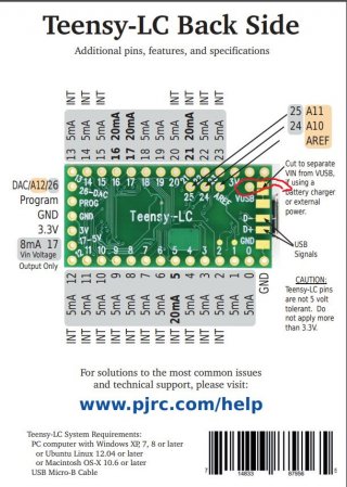
TEENSY LC BACK SIDE CARD.JPG

Are the pins in the picture above are what are Vin inputs?
Also can I have an external power source plugged in and
have the usb port plugged in at the same time?

Thanks.
 

Attachments

  • card6b_rev1.pdf
    358.5 KB · Views: 75
Vin is the pin on the corner and feeds the rest of the LC, V-USB is the power coming from the USB jack. In default configuration they are connected and Teensy is powered from USB and other parts can get SUB 5V from the Vin pin up the the port limit.

If you are doing what you are trying you cut the trace or come up with some other method to avoid problems with connecting two power supplies together and connect power in to VIN to power the board.

Note that an LC does not need 5V for anything so if everything else in this project is 3.3V a more efficient option may be to supply 3.3V to the 3.3V pin and power the Teensy that way. In which case VIN has nothing on it unless USB cable is connected. If doing so you need to be very careful that it never rises above 3.3V since that will kill the LC, and work out what happens if USB is connected while 3.3V power is off (will the Teensy internal 3.3V reg try to power the rest of the circuit and fail). If not confident designing a power circuit that doesn't over-run slightly on startup then the 5V power option may be easier.
 
I'm going to be using this wireless serial module which also runs of off 3.3 volts. The step down converter I'm going to be using will power the Teensy LC and this module.

The power will come from the 6 volt solar panel. Unfortunately I can't power everything off of 3.3 volts since the motors I will be powering are rated for 6 volts.

I was hoping to be able to plug in the USB to monitor my readings via serial monitor and power the Teensy LC with the step down converter at the same time. Is there anyway to do this?

I don't want to have to disconnect the Teensy LC from the stepdown converter every time I have to troubleshoot via USB serial monitor to confirm some values.

https://grabcad.com/library/hc-12-si4463-wireless-serial-module-1
 
Hi I did cut that trace.

Does the Teensy LC have any lights to confirm power is on?

I then hooked it up via the micro USB port to the pc and it didn't connect or power on until I used a small wire to connect the Vin and usb points together. So do I have to hook up a diode?

Basically if I power this with my 3.3 volt step down converter to the Vin port and ground pin it should turn on?
Then if I hook up the diode between the Vin and usb leads, I can hook up the micro USB cable to the pc and read data from the Teensy LC?

The 2nd diode mentioned in another post on the link above
really confused me. Does that hook up to the USB cable?
 
I just realized putting in the diode as it says on the other thread will drop voltage by .3 volts. So that'll mess up the voltage being sent by my 3.3 volts step down converter?
 
Except for the Pin 13 LED under program control - there are no LEDS/lights showing power on a Teensy.

If only power is USB - and with trace cut a wire connects the VIN and the internal VUSB then no diode is needed - that just completes the circuit opened when the trace was cut.

The CARD shows VIN spec as 3.7 to 5.5 volts - so operation under 3.7 volts would be out of spec - operation would be suspect at 3.3V.

If you trust the 3.3V step down to supply clean and proper voltage - AFAIK that could be placed on the 3.3V pin to power the Teensy (and trace cut before applying powered USB cable). But if the voltage doesn't maintain at 3.3V the Teensy is at risk.

Cutting the trace leaves USB fully functional for connection to micro USB to PC - but requires external power applied to VIN pin to power the Teensy and no DIODES are required with no connection between VIN and VUSB.

IIRC PJRC.com does show a Teensy 2 (?) with twin diodes to block power feedback in both directions. A single diode can work one direction - but that or a second diode on a T_LC isn't my forte. But yes, a diode will drop voltage in the forward direction while stopping it in the reverse direction.

<edit>: https://www.pjrc.com/teensy/external_power.html at "Option #3: Two 1N5817 Diodes" does explain the second diode.
 
Thanks your info clears things up a lot.

I was confused by the 5 volt notation on the board and whether or not it was Vin. In this case I will use the 3.3 volt pin. I used a multimeter and DC power supply to verify clean output value of 3.27 volts on the step down converter.

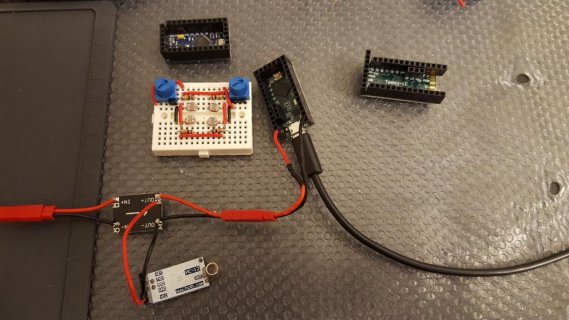
I've attached a picture to give a broader view of what I'm doing.

Basically I was previously using two arduino pro minis at 3.3 volts and 8 mhz and communicating between them using the hc-12 wireless serial modules.
1 arduino pro mini and 1 hc-12 module were being powered by a 6 volt solar panel.

One arduino pro mini was sending analog values from 4 light dependent resistors and 2 potentiometers.
The other arduino pro mini was receiving those values and the code was driving two h-bridge modules and two DC motors.

The problem with the arduino pro mini was I couldn't connect a micro USB port simultaneously and power source at the same time due to pin quantity limitations and also connecting a USB to serial ttl connector everytime was a hassle. This made it hard for me to update code and troubleshoot my project.

Basically I wanted to find out if my 6 volt solar panel is providing enough power and also what kind of values my 4 light dependent resistors and 2 potentiometers are putting out. That'll help me determine why my motors are not rotating.

So the reason why I got the Teensy LC is that it has a micro USB connector for uploading code and using the serial monitor and so I can determine if I'm getting enough power at the same time. I've got a screenshot of my intended setup that I'll post later.

Question I'm wondering is if this is right?
 
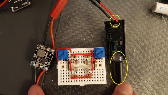
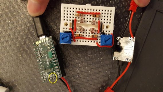
I've attached pictures this time.
Still a newbie to the forum so I can't find figure out how to edit current posts.

So if I understood things correctly?:
1. I cut the VIN and USB trace
2. I plugged the power from the step down converter to the 3.3 volt pin and gnd pin shown in pictures

THIS LAST PART IS CRITICAL FOR MY APPLICATION
3. The teensy LC usb port can still be plugged into the pc and draw power from the 3.3 volt step down converter simultaneously?
20180208_002818.jpg

20180210_170217.jpg

20180210_170241.jpg
 
As long as you have a common ground the intent is that USB will work no matter how the Teensy is powered - internal 3.3V reg our external supply.
 
#3 wont draw power, but will still pass signals to the usbserial port which is obviously fine, the usb power will never be used once that trace is cut

if you prefer to not cut the trace for portability purposes, you can modify a usb cable, strip the shield, and cut the red wire, seal and secure it so it wont touch the shield inside the cable and your done.

this will allow you to use that cable with your setup, without needing to cut the trace.

later on if you want to remove teensy and reprogram it externally or for another project, you can change to a non modified usb cable and reprogram it like normal
 
Status
Not open for further replies.
Back
Top