Multiple SPI Devices - Two's Good, Three's a Crowd

Status
Not open for further replies.

randomvibe

Well-known member
My Teensy3.6 with three SPI devices is having difficult intermittent problems.

On one hand I have a Teensy 3.6 project with two SPI devices that work solidly in a program for-loop: an IMU (LSM6DS3), and a display (ILI9341).

Separately, I hooked up a PIXY camera on another Teensy 3.6 with SPI. After some setup, the communication is solid and the Teensy echoes back tracking information in a for-loop.

When I merge all three SPI devices on MISO0/MOSI0/SCK0 with separate SS channels, the PIXY SPI readings are only spotty. Tracking information is intermittently missed. When I remove the ILI9341 display, the problem persists. To my surprise, when I reconnect the display and remove the IMU, the PIXY readings are solid.

Each device uses a different SS channel. See code below. I lowered the IMU speed from 10MHz to the PIXY speed of 1MHz, but no luck. What can go wrong with multiple SPI devices at different speeds sharing the same SPI ports?

Code:
// LSM6DS3 IMU
#define   READ    0x80  
#define   WRITE   0x00
#define   MOSIX   11
#define   SCKX    13
#define   MISOX   12
#define   CSX     15    // SS channel

SPISettings IMUSPI(10000000, MSBFIRST, SPI_MODE0);    // 10MHz


// ILI9341 DISPLAY
#define   TFT_CS      10   // SS channel
#define   TFT_DC      9
#define   TFT_RST     255  

ILI9341_t3 tft = ILI9341_t3(TFT_CS, TFT_DC, TFT_RST, MOSIX, SCKX, MISOX);


// PIXY Teensy 3.5/3.6 SPI Pins
#define  PIXY_SPI_CS   20        // SS channel

SPISettings PIXYSPI(1000000, MSBFIRST, SPI_MODE0);   // 1MHz


void spi_initialize()
{
    pinMode(CSX, OUTPUT);
    digitalWrite(CSX,HIGH);
    
    pinMode( PIXY_SPI_CS, OUTPUT);
    digitalWrite( PIXY_SPI_CS,HIGH);
 
    SPI.setMOSI(MOSIX);
    SPI.setMISO(MISOX);
    SPI.setSCK(SCKX);
    SPI.begin(); 

}
 
its worth pointing out some devices dont release the MISO line properly, and will need to be tri-state buffered
 
its worth pointing out some devices dont release the MISO line properly, and will need to be tri-state buffered

Yes, a very good point. These SPI devices cause a lot of trouble!

You can check for these with a voltmeter and 2 resistors. Connect both resistors to MISO, with one to GND and the other to 3.3V. When no SPI device is active, you should measure 1.6V on the MISO signal due to the resistors. If you see a logic high or low, the somebody is erroneously driving MISO. If you find this, usually the 2 solution are adding a tri-state buffer, or connecting the misbehaving chip to its own SPI port. Fortunately you have 3 separate ports with Teensy 3.6. :)

As I pointed out, the three SPI devices work solidly on their own, including pairing the ILI9341 display and IMU. I did try adding 10K pull-ups at each chip-select channel as this site suggested, but no luck.

Problem solved using a separate SPI port. My crowded project required reassigning pins to access MISO1/MOSI1/SCK1/CS1, but it was well worth it. Object-detection information flow to Teensy3.6 is solid.

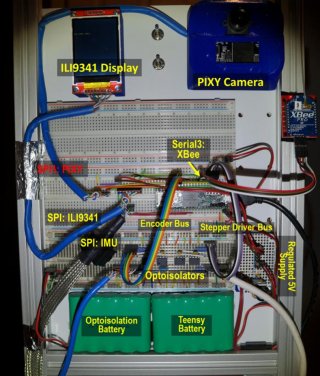
Image below shows the ILI9341 and IMU sharing the default SPI port, and PIXY on SPI1. If I decide to add more SPI devices, I'll have to test out a tri-state buffer because that may be easier than accessing SPI2 on the bottom pads.

fur20180218b.jpg

I had trouble connecting to SPI1 because it's not sufficient specifying those pins. Function-calls require the "SP1" identifier. See code below:

Code:
// LSM6DS3 IMU
#define   READ    0x80  // general SPI transfer bits
#define   WRITE   0x00
#define   MOSIX   11
#define   SCKX    13
#define   MISOX   12
#define   CSX     15   // chip select

SPISettings SETA(10000000, MSBFIRST, SPI_MODE0);   // 10MHz

// ILI9341 DISPLAY
#define   TFT_CS      10  // chip select
#define   TFT_DC      9
#define   TFT_RST     255  // unused pin, connect to 3.3V

ILI9341_t3 tft = ILI9341_t3(TFT_CS, TFT_DC, TFT_RST, MOSIX, SCKX, MISOX);


// PIXY Camera:
#define   PIXYHWSPI     SPI1
#define   PIXY_MOSIX    0
#define   PIXY_SCKX     32
#define   PIXY_MISOX    1
#define   PIXY_SPI_CS   31        // SPI Chip Select

SPISettings PIXYSPI(1000000, MSBFIRST, SPI_MODE0);   // 1Mhz


void spi_initialize()
{
    // INITIALIZE SPI
    pinMode(CSX, OUTPUT);
    digitalWrite(CSX,HIGH);
    
    SPI.setMOSI(MOSIX);
    SPI.setMISO(MISOX);
    SPI.setSCK(SCKX);
    SPI.begin(); 
    delayMicroseconds(100000);

    // INITIALIZE PIXY SPI
    pinMode( PIXY_SPI_CS, OUTPUT);
    digitalWrite( PIXY_SPI_CS,HIGH);
 
    PIXYHWSPI.setMOSI(PIXY_MOSIX);
    PIXYHWSPI.setMISO(PIXY_MISOX);
    PIXYHWSPI.setSCK(PIXY_SCKX);
    PIXYHWSPI.begin(); 
    delayMicroseconds(100000);

}


uint16_t  pixy_spi_read_16bit(uint16_t target, SPISettings SETX, uint8_t CS)
{
    uint8_t   a, b;
    uint16_t  c;

    // Read First Byte
    PIXYHWSPI.beginTransaction(SETX);      
    digitalWrite(CS,LOW);    
    a = PIXYHWSPI.transfer(target);    
    PIXYHWSPI.endTransaction();

    // Read Second Byte
    PIXYHWSPI.beginTransaction(SETX);
    b = PIXYHWSPI.transfer(0x00);              
    digitalWrite(CS,HIGH); 
    PIXYHWSPI.endTransaction();

    // Build Pixy 16-bit Word 
    c = (uint16_t)(b | (a<<8));

    return  c;
}
 
Last edited:
Status
Not open for further replies.
Back
Top