SPI communication with DAC MAX532 from Teency 3.5

Status
Not open for further replies.

Lorenzo

Well-known member
Hello forum,

I am opening a new post about SPI communication with DAC since I am not able to solve the following problem since two weeks.

I am trying to communicate with a DAC MAX 532 from Teency 3.5 https://datasheets.maximintegrated.com/en/ds/MAX532.pdf

Here is my code:
Code:
#include <SPI.h>

int channel_A = 0;
int channel_B = 0;
float pi=3.14;
float freq=1.0f;
int cycles=0;

// set pin 10 as the slave select for the digital pot:
const int slaveSelectPin = 10;

void setup() {
  Serial.begin(115200);

  pinMode(slaveSelectPin, OUTPUT);

  SPI.setMOSI(11);
  //SPI.setMISO(12);
  SPI.setSCK(13);
  
SPI.begin();
}


void loop() {
  

      float t=millis()/1000.0f;
      
      channel_A=(int) (2000.0f*sin(t*2*pi*freq)+2000.0f);
      channel_B=(int) (2000.0f*sin(t*2*pi*freq+pi/2)+2000.0f);
      
      SPI_write(channel_A, channel_B);
      delay(1000); // THIS IS THE DELAY I MODIFIED

}

void SPI_write(int channel_A, int channel_B) {

  byte byte_0 = channel_B >> 4;
  byte byte_1 = ( channel_B << 4 ) | ( channel_A >> 8 );
  byte byte_2 = channel_A & 255;
    
  digitalWrite(slaveSelectPin, LOW);
  delayMicroseconds(1);
  SPI.transfer(byte_0);
  SPI.transfer(byte_1);
  SPI.transfer(byte_2);
  delayMicroseconds(1);
  digitalWrite(slaveSelectPin, HIGH);
  delayMicroseconds(1);
  
//  printByte(byte_0);
//  Serial.print("; ");
//  printByte(byte_1);
//  Serial.print("; ");
//  printByte(byte_2);
//  Serial.println(); 
}

void printByte (byte val)
{
  for (byte mask = 0x80; mask; mask >>= 1)
  {
    Serial.print (val & mask ? '1' : '0');
  }
}


The problem was originally posted here: https://forum.pjrc.com/threads/49799-DAC-on-Teency-3-5
But at that time I was thinking the signal was noisy due to some problems in the circuit or with the grounding.

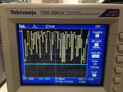
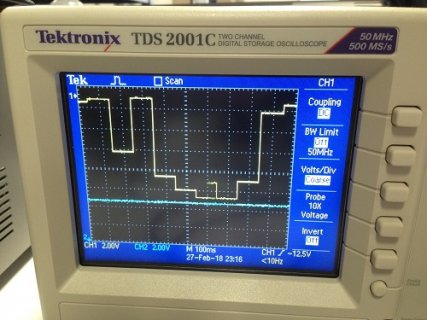
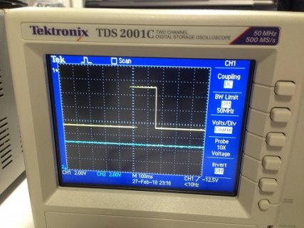
Currently I have tryed to change the "delay" in the void loop and those are the signals (please see attached pictures) I get from the scope with different values of the delays. I can not understand why the signal does not mantain a shape of a sin wave but oscillate so much.
By increasing the delay the signal doesn't look noisy so I am quite sure the problem is not in the hardware connections but in the software.

What is there wrong in the SPI communication?
Is there a timing problem?

I would really appreciate if you could look into this matter.
Thank you for your help. :)
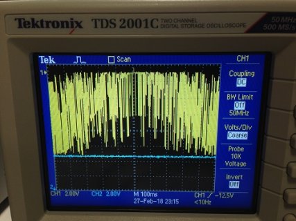
delay1.JPG
delay10.JPG
delay100.JPG
delay1000.JPG
 
I see nowhere in your code a setting for the SPI clock... Normally you would define a SpiSettings struct and call SPI.beginTransaction with this struct to be sure that your SPI clock, bit mode, and bit order is correct.

For the MAX532 you could insert SPISettings setMAX532(2000000, LSBFIRST, SPI_MODE0) before setup().

And then in your function SPI_write(...) add SPI.beginTransaction(setMAX532) as very first line and SPI.endTransaction() as very last line.

A second problem is that you seem (but I might be wrong) sending the data in the wrong order. The first byte which you send (byte_0) should have the 8 LSBs from channel_A, byte_1 should have the 4 MSBs of channel_A followed by the 4 LSBs of channel_B left shifted by 4, and byte_2 the 8 MSBs of channel_B.

For example byte byte_0 = (channel_A && 0xFF); byte byte1 = (((channel_A >>8 & 0xF) | ((channel_B & 0xF) << 4)); byte byte_2 = ((channel_B >> 4) & 0xFF);

If I were you, I'd try to narrow these problems down by leaving (temporarily) channel_B = 0 always, then make sure that your SpiSettings and byte splitting are correct for channel_A only. After that, you might add channel B again.
 
Last edited:
I see nowhere in your code a setting for the SPI clock... Normally you would define a SpiSettings struct and call SPI.beginTransaction with this struct to be sure that your SPI clock, bit mode, and bit order is correct.

For the MAX532 you could insert SPISettings setMAX532(2000000, LSBFIRST, SPI_MODE0) before setup().

And then in your function SPI_write(...) add SPI.beginTransaction(setMAX532) as very first line and SPI.endTransaction() as very last line.

A second problem is that you seem (but I might be wrong) sending the data in the wrong order. The first byte which you send (byte_0) should have the 8 LSBs from channel_A, byte_1 should have the 4 MSBs of channel_A followed by the 4 LSBs of channel_B left shifted by 4, and byte_2 the 8 MSBs of channel_B.

For example byte byte_0 = (channel_A && 0xFF); byte byte1 = (((channel_A >>8 & 0xF) | ((channel_B & 0xF) << 4)); byte byte_2 = ((channel_B >> 4) & 0xFF);

If I were you, I'd try to narrow these problems down by leaving (temporarily) channel_B = 0 always, then make sure that your SpiSettings and byte splitting are correct for channel_A only. After that, you might add channel B again.

Thank you very much Theremingenieur!! :D :D
This solves my problem!

I have added the following line at my code and the "begin" and "end" transactions lines:
SPISettings setMAX532(2000000, MSBFIRST, SPI_MODE0);
Bytes were sent in the correct order.

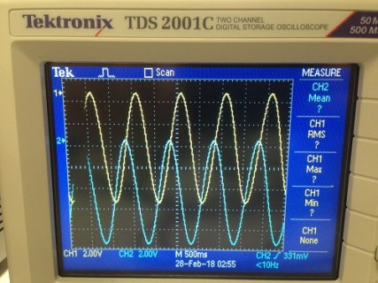
Here is the final version of the code that allows to obtain two sine waves with a DAC MAX 532 from Teency 3.5, and the image of the resulting signals on the scope.

Code:
#include <SPI.h>

uint16_t channel_A = 0;
uint16_t channel_B = 0;
float pi=3.14;
float freq=1.0f;

int cycles=0;
unsigned long t;
unsigned long t0=0;
unsigned long delta_t;

unsigned long t2;
unsigned long t02=0;
unsigned long delta_t2;  

const int slaveSelectPin = 10;

SPISettings setMAX532(2000000, MSBFIRST, SPI_MODE0);

void setup() {
  Serial.begin(115200);
  pinMode(slaveSelectPin, OUTPUT);
   
  SPI.setMOSI(11);
  //SPI.setMISO(12);
  SPI.setSCK(13);
  
  SPI.begin();
  t=millis();
  }
     
void loop() 
{
      t=millis();
      delta_t=t-t0;   
      
      if (delta_t>=1)
      {
      float ti=millis()/1000.0f;
      
      channel_A=(int) (2000.0f*sin(ti*2*pi*freq)+2000.0f);
      channel_B=(int) (2000.0f*sin(ti*2*pi*freq+pi/2)+2000.0f);
       
      SPI_write(channel_A, channel_B);
      t0=t;
      }
  
}

void SPI_write(uint16_t channel_A, uint16_t channel_B) 
{
  byte byte_0 = (byte) (channel_B >> 4);
  byte byte_1 =(byte) ( ( channel_B << 4 ) | ( channel_A >> 8 ));
  byte byte_2 =(byte) ( channel_A & 0xFF);

  SPI.beginTransaction(setMAX532);
  digitalWrite(slaveSelectPin, LOW);
  delayMicroseconds(1);
  SPI.transfer(byte_0);
  SPI.transfer(byte_1);
  SPI.transfer(byte_2);
  delayMicroseconds(1);
  digitalWrite(slaveSelectPin, HIGH);
  delayMicroseconds(1);
  SPI.endTransaction();
  
//  printByte(byte_0);
//  Serial.print("; ");
//  printByte(byte_1);
//  Serial.print("; ");
//  printByte(byte_2);
//  Serial.println(); 
}

void printByte (byte val)
{
  for (byte mask = 0x80; mask; mask >>= 1)
  {
    Serial.print (val & mask ? '1' : '0');
  }
}

sine.JPG
 
Thank you very much Theremingenieur!!
This solves my problem!


You could have found that by yourself by systematically reading the SPI library page within the Teensyduino reference on the PJRC website...
 
Status
Not open for further replies.
Back
Top