DavidJohnston
Member
Source code : Inline and attached.
Error Messages: None
Hardware: Teensy3.5
Wiring: Pulse and Direction pins to a DM320T driving a stepper (this works fine). A and B signals from a rotary encoder to pins. 20V for the DM320T driver. 5V supply for the opto isolator and rotary encoder LED. Teensy powered over USB.
I'm trying to get a rotary encoder working. It provides two quadrature signals (A and B). The four high low pair combinations LL,HL,HH,LH that cycle around as the encoder moves lets the software record the movement by tracking the quadrature changes.
When sampling rising and falling edges on a binary signal, the number of ups must match the number of downs +- 1.
Also, since the A signal and B signal move with a 90 degree phase difference, the numbers of ups and downs on the A and B signals must match +- 1.
I found the encoder motion was not correctly being recorded. So I started digging. In order to help diagnose this, I attached A and B each to two pins. I set interrupts on all four pins. 2 set to record the rising edges of A and B. 2 set to record the falling edges of A and B. The position is kept, modulo 1200, which is the number of steps in 360 degrees.
An example output is this: (Postion, A rising count, A falling count, B rising count and C falling count).
POS :800
AR :1207 AF:1217
BR :1206 BF:1209
You can clearly see that the number of rising and falling edges differ by a lot more than one. Over time the position (which should be near the zero point so 1190 ish to 10ish) has drifted to 800 (positive is CCW) so it's dropping edges, rather than gaining them.
The values touched by the ISRs are volatile as they should be:
Code:
int rotary_encoder_pin_a_r = 20;
int rotary_encoder_pin_b_r = 10;
int rotary_encoder_pin_a_f = 19;
int rotary_encoder_pin_b_f = 9;

volatile int rotary_encoder_pos = 0;
volatile int br_count=0;
volatile int ar_count=0;
volatile int bf_count=0;
volatile int af_count=0;
The interrupt setup code is this:
Code:
  pinMode (rotary_encoder_pin_a_r , INPUT_PULLUP );
  pinMode (rotary_encoder_pin_b_r , INPUT_PULLUP );
  pinMode (rotary_encoder_pin_a_f , INPUT_PULLUP );
  pinMode (rotary_encoder_pin_b_f , INPUT_PULLUP );
  void do_rotary_encoder_a_r();
  void do_rotary_encoder_b_r();
  void do_rotary_encoder_a_f();
  void do_rotary_encoder_b_f();
  attachInterrupt(rotary_encoder_pin_a_r , do_rotary_encoder_a_r , RISING) ;
  attachInterrupt(rotary_encoder_pin_b_r , do_rotary_encoder_b_r , RISING) ;
  attachInterrupt(rotary_encoder_pin_a_f , do_rotary_encoder_a_f , FALLING) ;
  attachInterrupt(rotary_encoder_pin_b_f , do_rotary_encoder_b_f , FALLING) ;
The interrupt service routines are:
Code:
void do_rotary_encoder_a_r() {
  int b;
  int inc;
  ar_count++;
  b = digitalRead(rotary_encoder_pin_b_r);
  if (b == LOW) {
    inc=1;
  } else {
    inc=-1;
  }

 cli();
 rotary_encoder_pos = (rotary_encoder_pos + inc) % 1200;
 sei();
}

void do_rotary_encoder_b_r() {
  int a;
  int inc;
  br_count++;
  a = digitalRead(rotary_encoder_pin_a_r);

  if (a == HIGH) {
      inc=1;
  } else {
      inc = -1;
  }

  cli();
  rotary_encoder_pos = (rotary_encoder_pos + inc) % 1200;
  sei();
}

void do_rotary_encoder_a_f() {
  int b;
  int inc;
  af_count++;
  b = digitalRead(rotary_encoder_pin_b_r);

    if (b == HIGH) {
      inc=1;
    } else {
      inc=-1;
    }
 cli();
 rotary_encoder_pos = (rotary_encoder_pos + inc) % 1200;
 sei();
}
These are written to keep the critical section minimized. So the code decides whether to increment to decrement the position then applies the change in a one liner at the end, with interrupts off.
Keep in mind that each ISR runs mutually exclusive with the others because the A and B signals rise and fall only one at a time.
The falling edges appear to have been captured more reliably, but not perfectly.
The rising edges are dropped at a higher rate than the falling edges.
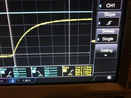
I looked at the waveforms on a scope and the falling edge was solid, but the rise time using the internal pullup was 4us. I reduced this to 2us with external 5k pullups. This reduced but didn't eliminate the dropping completely.

I also changed my code to turn off serial comms while sampling the rotations to eliminate interrupt interference.
So there appears to be some sort of bug in the chip, where pins generating interrupts on the rising and falling edges of the same signal (rising on one pin, falling on the other) manage to miss some of the transitions. This should be impossible. It implies for example, getting two falling interrupts without an intervening rising interrupt.
A longer example of the position drifting and the counts differing is below:
Code:
POS  :388
AR  :2  AF:1
BR  :1  BF:2
---------
POS  :358
AR  :1201  AF:1211
BR  :1199  BF:1207
---------
POS  :328
AR  :1197  AF:1215
BR  :1196  BF:1199
---------
POS  :297
AR  :1196  AF:1211
BR  :1196  BF:1200
---------
POS  :271
AR  :1199  AF:1208
BR  :1197  BF:1200
---------
POS  :305
AR  :1213  AF:1233
BR  :1213  BF:1217
---------
Does anybody have experience with this sort of problem or suggestions?
Are the pin transition detector particularly sensitive to slow edges?
Did I miss something in the interrupt code?
Thanks,
David

