Teensy 3.2 - DC DC converter troubles

Status
Not open for further replies.
Hi, all! I'm hoping for a bit of guidance on what appears to be a basic misunderstanding on my part. The goal here is to use an IR0512S to convert +5v to +/-12v and then feed these into an op amp to send control voltage information to a synth. I have everything working on a 0 to 5v scale and wanted to be able to extend the voltages with only usb power to cover more range for CV control. A friend is doing this with the IR0512S, but for some reason I can't figure out what I'm doing wrong even though it seems our setups sound identical. Now onto the specifics of the problem:

On the Teensy 3.2 I'm using VUSB and GND for the + and - rails on the breadboard. It measures predictably around 5v.
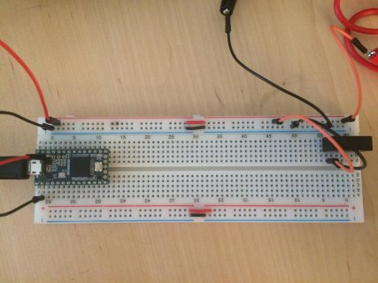
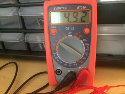
teensy_bb.jpg teensy_mm.jpg

When I feed this information into the IR0512S following the datasheet the output voltage is way higher than 12v! In the picture you'll notice the "common" pin is not connected to GND, but I did try that configuration with no success. I'm sure it will be needed in the final design, but for now I just want the output voltage from the IR0512S to read correctly.
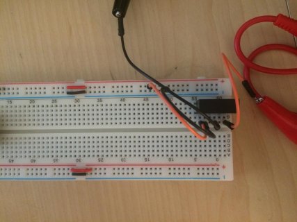
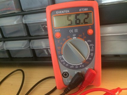
dcdc_bb.jpg dcdc_mm.jpg dcdc_pins.jpg

Any thoughts on what I'm doing incorrectly would be greatly appreciated!
 
The data sheet does say that operation at no load may not meet all specifications.
56V does seem a bit extreme, but try loading it with a resistor. The dual supply may need a resistor to common from each output, though that is just a guess as I don't know anything about the converters internals.
 
Yikes, 56 volts!

Indeed the datasheet says "none" for minimum load, but has this footnote:

1. Operation at no load will not damage unit but it may not meet all specifications.

Looks like "not meet all specifications" means "output more than double rated voltage". This sort of dishonesty is pretty typical for datasheets trying to make a sale rather than give useful info. Obviously they felt not requiring a minimum load, as is common for these types of converters, would be a good selling point. But now you're left with having to guess what the minimum load needs to be get this thing to actually operate within spec. A real min load spec would have been much more helpful. I'd try between 1% to 5% of the max current.

Another common gotcha with these little converters is the need for capacitors. But bigger is not always better, especially if you put big caps on the output but none on the input. I'd suggest trying 10uF at the input. Getting it close to the input pins matters, but don't worry too much about the distance of just a couple breadboard pins. The output is likely to have a lot of noise if you don't add output capacitors there too. Be careful not to add more than you need, since this converter doesn't claim to have any sort of soft-start feature (another omission in the datasheet...)
 
Thanks for the quick response, guys! It's much appreciated. I'm pretty new to all of this, but I'll see if I can make sense of everything and put all your advice to use. Currently all I own are 0.1uf capacitors so I'll have to go shopping before I can test anything further. I'm still pretty confused about how my friend was able to get this thing purring out +/-12v and mine is trying to kill me. :) Also, if you know of a better way to get a +/-12v signal from usb power only, then I'm all ears!
 
Some cheap switched mode power supplies or converters can output short but ugly and dangerous voltage spikes. That's why (as a rule of thumb) you should always load the outputs with 1/10 of the rated output current. The IR0512S is rated for 125mA, so you should try to eat up at least 12.5mA before you connect whatever meaningful load. That means that two 820R resistors, one from +12V to GND and one from -12V to GND should guarantee safe operation by drawing the first 14.6mA. You should use 1/4W types for the resistors and expect to "waste" 350mW in moderate heat, but this will allow you safe operation of all connected circuitry.
 
Wow, that murata part has this on page 4 of its datasheet.

The minimum load to meet datasheet specification is 10% of the full rated load across the specified input voltage range. Lower than 10% minimum loading will result in an increase in output voltage, which may rise to typically double the specified output voltage if the output load falls to less than 5%.
 
Wow, that murata part has this on page 4 of its datasheet.

So does that mean it's not really input 5v to ouput +/-12v? It's input 10% of 5v to output +/-12v, but don't drop below that because the further you drop below 10% the more likely you are to double/triple (or more) your desired output voltage?
 
It has input 5V and output +/-12V. If the outputs are loaded with between 10 and 100% of the nominal current. This can be achieved by the simple adding of two resistors as I wrote above. If there is not enough load, the output regulation can‘t work.

Don‘t confound output voltages and current loads. These are completely different things.

You might compare this to a car motor which will just run fine between 800 and 6000 rpm. If you force it below, it will stall and stop working.

Ah, okay. Thanks for clearing that up for me!
 
Some cheap switched mode power supplies or converters can output short but ugly and dangerous voltage spikes. That's why (as a rule of thumb) you should always load the outputs with 1/10 of the rated output current. The IR0512S is rated for 125mA, so you should try to eat up at least 12.5mA before you connect whatever meaningful load. That means that two 820R resistors, one from +12V to GND and one from -12V to GND should guarantee safe operation by drawing the first 14.6mA. You should use 1/4W types for the resistors and expect to "waste" 350mW in moderate heat, but this will allow you safe operation of all connected circuitry.

Theremingenieur, thanks so much for this information. I have a few questions as I'd like to better understand further what I'm doing rather than ask for exact solutions. (anyone can chime in)

1. Can you explain the math I would use to conclude that an 820r resistor is the correct load?

2. Unfortunately, the closest resistors I have to 820r are 680r and 1k, but I still wanted to do some testing. If I connect 2 680r resistors from GND to the +12v and -12v rail it drops the multimeter reading down to around 16.1v when feeding the input 3.3v instead of 5v. 1k offers higher readings and feeding it 5v as an input reads around 20v on the multimeter with the 680r resistors. How do I continue to drop the output voltage to the desired 12v range?

3. Most importantly to me, is this commercially safe/smart for a user-based product? The potential end goal could be to include this as an addition to a current project, and I don't want to waste time on a bad idea. The idea here being I'm trying to find a way to produce +/-12v from usb only.
 
1. I need to draw at least 1/10 of the maximal current of 125mA, which is 12.5mA. 12V / 12.5mA = 960R (Ohm‘s law). Since I may draw more than that minimal current, but not less, I‘ll take the next smaller resistor value in the E12 resistor series which every circuit designer should have at hands or in the drawer and which is 820R. You might take a smaller resistor, for example 680R since you may draw more current, but not less. But then, there is the thermal power problem, since higher current means more heat: 12V / 680R = 17.65mA which at 12V corresponds to a power dissipation of 211mW, so you should still be fine with the 1/4W version of these resistors.

2. It seems extremely strange to me that even with the increased load by the smaller 680R resistors, you seem still to have a too high voltage. It might be that your digital multimeter is giving wrong readings, knowing that the output of these SMPS is not pure DC but has RF noise and switching spikes added. That‘s why I would not only rely on the multimeter, but do a second check with an oscilloscope. But to me, it looks rather like you‘ve got a defective or otherwise bad part (or it broke because you let it initially run without load which happens rarely) and I‘d tend to replace the thing. For this reason, I never order single quantities of a component but always two or three identical parts to allow a differential diagnose.

3. Your concept is basically not bad at all. Bob Moog used similar circuits in his Moogerfooger effect pedals. Buthe added some additional stuff to make it even more safe: These pedals can be operated from a 9V Block battery. These 9V are then regulated down to stabilized 5V through a linear 7805 regulator. You would not need this first step, since you have already stable and regulated 5V from the USB port. In a second step, these 5V are fed into a similar SMPS as you use, but which gives +/-15V. Then, there are the minimal load resistors and in parallel of these 78L12 and 79L12 linear regulators which convert these noisy and not always stable +/-15V into clean +/-12V. And this concept has been used in several tens of thousands of these effect devices, sold for heavy duty stage use. Thus, it should also work for you.
 
1. Thanks for showing the math - that really helps!

2. Luckily I have 2 of these IR0512S's but they are both behaving the same way with the 680r resistors. You have a good point about the digital multimeter, though. Unfortunately, I don't own an oscilloscope.

3. Thanks for this as well! I'll look into acquiring some linear voltage regulators too.
 
Status
Not open for further replies.
Back
Top