Hi everyone. Glad to have found this resource. I'm working on building a MIDI Controller using a Teensy LC nearly exactly as this...
https://ask.audio/articles/how-to-build-a-simple-diy-usb-midi-controller-using-teensy
The only difference is I'm planning to use LED Arcade Buttons which will simply be lighted at all times (no control needed). These...
https://www.adafruit.com/product/3490
I'd like to power the entire box with one USB connection from a powered hub advertised to provide 900mA per output. This one...
https://www.apple.com/shop/product/HHM72ZM/B/belkin-aluminum-usb-30-4-port-hub?afid=p238%7Cs9WxpDgaK-dc_mtid_1870765e38482_pcrid_246387003261_&cid=aos-us-kwgo-pla-btb-3pp--slid--product-HHM72ZM/B
Also connected to the hub will be an iPod Touch running Loopy HD to be controlled with this MIDI controller.
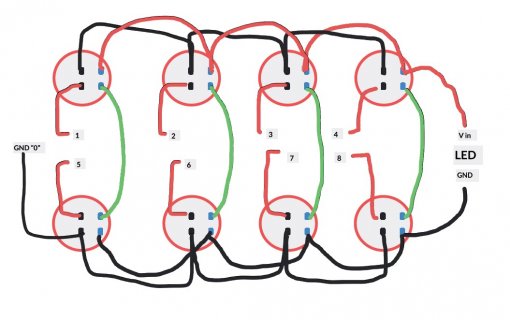
So far I'm pretty solid on the code and loading it into the Teensy LC. My only real question is about powering the LED's. Here's my (ahem) wiring diagram...

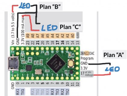
The LEDS are rated for 10mA/5v and 2mA/3.3v - eight of them total. I'm going to run a 900mA USB to the Teensy and power the series/parallel LED's (2.5v each) between pin 17 (5v) and the nearby adjacent GND pin. So, assuming the LED's aren't too dim at 2.5v, I should only need less than 16mA for the LED's. If I need to run the eight LED's at 5v, then it will be 80mA. Will pin 17 cary 80mA?? Or even 16mA for that matter?? Reading the documentation it seems the pin 17 output is only good for 20mA. Or am I missing something? Is pin 17 simply a parallel connection to USB power?
Cheers! And thanks in advance.
https://ask.audio/articles/how-to-build-a-simple-diy-usb-midi-controller-using-teensy
The only difference is I'm planning to use LED Arcade Buttons which will simply be lighted at all times (no control needed). These...
https://www.adafruit.com/product/3490
I'd like to power the entire box with one USB connection from a powered hub advertised to provide 900mA per output. This one...
https://www.apple.com/shop/product/HHM72ZM/B/belkin-aluminum-usb-30-4-port-hub?afid=p238%7Cs9WxpDgaK-dc_mtid_1870765e38482_pcrid_246387003261_&cid=aos-us-kwgo-pla-btb-3pp--slid--product-HHM72ZM/B
Also connected to the hub will be an iPod Touch running Loopy HD to be controlled with this MIDI controller.
So far I'm pretty solid on the code and loading it into the Teensy LC. My only real question is about powering the LED's. Here's my (ahem) wiring diagram...

The LEDS are rated for 10mA/5v and 2mA/3.3v - eight of them total. I'm going to run a 900mA USB to the Teensy and power the series/parallel LED's (2.5v each) between pin 17 (5v) and the nearby adjacent GND pin. So, assuming the LED's aren't too dim at 2.5v, I should only need less than 16mA for the LED's. If I need to run the eight LED's at 5v, then it will be 80mA. Will pin 17 cary 80mA?? Or even 16mA for that matter?? Reading the documentation it seems the pin 17 output is only good for 20mA. Or am I missing something? Is pin 17 simply a parallel connection to USB power?
Cheers! And thanks in advance.


