Serial Plotting Issue with T3.6

Status
Not open for further replies.

128ITSH

Active member
Hello everyone.
I am working on a teensy 3.6 based oscilloscope. I know that it will be limited but in the near time I am not going to need anything more than the 1MHz range.
I already got a working code, which gives about 800KSps:
(problematic serial function in the bottom)
Code:
//This sketch is a try to see how many samples can get transmitted from the teensy in one second
//samples are running for one second, then stopped and number of samples is printed
#include "ADC.h"
#include "RingBufferDMA.h"

const int readPin = A9;

ADC *adc = new ADC(); // adc object

//dma buffer size. above this seem to have problems with the serial monitor.
const int buffer_size = 256;
//dma buffer
DMAMEM static volatile int16_t __attribute__((aligned(buffer_size + 0))) buffer1[buffer_size]; 


// use dma with ADC0
RingBufferDMA *dmaBuffer = new RingBufferDMA(buffer1, buffer_size, ADC_0); 


//timing variables
bool _start1 = false;
unsigned long beforeMillis = 0;
const unsigned long interval1 = 1000;
long nSamples = 0;

void setup() {

  pinMode(readPin, INPUT); //pin 23 single ended

  Serial.begin(2000000);
  
  //ADC0
  adc->setAveraging(1); // default is 4, we want as fast as possible
  adc->setResolution(8); // set bits of resolution
  adc->setSamplingSpeed(ADC_SAMPLING_SPEED::VERY_HIGH_SPEED);
  //library docs say ADC_CONVERSION_SPEED::VERY_HIGH_SPEED is out of specs. use HIGH_SPEED instead for safer operation
  adc->setConversionSpeed(ADC_CONVERSION_SPEED::HIGH_SPEED); 


  // enable DMA
  adc->enableDMA(ADC_0);

  dmaBuffer->start(&dmaBuffer_isr);

  while(!Serial.available()){}
  delay(100);
  adc->startContinuous(readPin);
 
      
  beforeMillis = millis();
  _start1 = true;
}

//loop only checks if 1 second elapsed from the start, if yes, set _start1 false and stop the adc convertion
void loop()
{
  if (_start1)
  {
    unsigned long _now = millis();
    if (_now - beforeMillis > interval1)
    {
      adc->stopContinuous(); //stop converting
      _start1 = false;
      Serial.println(""); //print results
      Serial.println("ended");
      Serial.print("Samples: ");
      Serial.println(nSamples);
    }
  }
}

void dmaBuffer_isr() //called everytime the buffer is full
{
  if(Serial.availableForWrite())
  {
     Serial.write((uint8_t *)buffer1, buffer_size);
     nSamples= nSamples+buffer_size;
  }
  dmaBuffer->dmaChannel->clearInterrupt();
}

With arduino's serial monitor the output is a fast sequence of mirrored ????? symbols. (the ADC input is tied to 3.3V)
However when I started working on a PC plotting software (in C#) the output was this sequence:
255
0
255
0
255
and so on...
After getting tired of programming by myself, I turned to a free, open source software called SerialPlot.
The result there is the same:
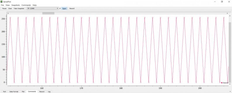
plot using software.jpg
If I tie the ADC input to 0V the output is jumping between 0 and 1 (no caps used, so I know it's okay that I get 1).
Same thing happens with a 1/2 voltage divider, output is changing between 0 and ~127.
The SerialPlot software settings are:
- No parity
- 8 bits
- 1 stop bit
- No Flow Control
Encoding:
Simple Binary
- N.O. Channels: 1
- Number type: uint8
- Endianness: Little Endian
Do you know what the problem could be? Encoding incompatibility? bad sketch code?

Thanks in Advance,
128ITSH
 
1. you have set the ADC to 8-bit, but your buffer1 is int16_t -- try setting that to int8_t.

2. your Serial.write() is trying to write uint8_t, so it will write one byte of the 16-bit buffer1 (high order byte will be 0), then 2nd byte of 16-bit word will be the value of the ADC (255)

3. Serial.wite() writes binary data, so on the IDE monitor output will be gibberish characters. You could use Serial.print() to print the values out as ASCII, e..g "255"

4. it's poor practice to print inside ISR's

5. there may be other problems ... i haven't actually run your sketch
 
Thanks for your quick reply!
- I should have noticed the buffer type, currently changing to int8_t doesn't compile, probably because the RingBufferDMA does not accept it. I will get into it tomorrow.
- The reason I use Serial.write() is that it can send a single buffer, as opposed to Serial.print() which requires looping through the whole buffer. The gibberish problem is solved in the SerialPlot software.
- I would like to know, why is it the poor practice to print inside an ISR?

Thank you for pointing this out for me,
128ITSH
 
Since the ADC is basically a unipolar 16bit device, it will always read uint16_t values and write these to 16bit registers, even if you select a lower resolution. Only after pulling them from the ring buffer, you might convert, or map these to signed 8bit values. What you are doing is printing bytes from the 16bit values, but since these are only filled with 8bit, every second reading gives a zero. Normal.

First, serial.print is extremely slow and blocks the ISR for too long time. Second, you should avoid function calls in general in ISRs, but only write „linear“ code inside. Function calls require the program flow to stop, save all the CPU registers on the heap, calculate the target address, jump there, do the required work, read the return address, jump there, restore the CPU registers from the heap, and continue running again. That‘s highly time wasting because an ISR is expected to return quickly, so that the main program flow can continue.

Didn‘t you read the whole documentation on the PJRC website before you started coding? Interrupts are covered here: https://www.pjrc.com/teensy/interrupts.html
 
Last edited:
Thank's for the clarification!
currently I can't find a way to convert the whole uint16_t[] buffer to a uint8_t[] buffer without the unneeded byte. However changing the encoding of the SerialPlot software to 16 bit values gets around this problem, however it is not efficient to write x2 more data than the actual readings so will be happy if there's a way to convert the whole 16 bit buffer to an 8 bit buffer while discarding one of the bytes without looping through the whole buffer.

The way I would get the function call out of the ISR is by moving it to loop(), and every time the ISR is called it will set a bool to true. this bool will be checked in loop() and whenever it's true, Serial.write() will be called and the bool will be set back to false. Is that the correct way?

You are right I should've read the docs, but I tend to rush things, fail, and then read/ask and learn. probably a less better way but that's who I am :D
 
To me, there seem to be only very few options to "convert" the buffer content without an additional looping in code. The "Gold standard solution" would be to modify the DMA transfer inside the ADC lib to transfer only the lower byte into the buffer which could then be set up as 8bit type. But fiddling around with other people's code without accidentally breaking important functionality is not everybody's cup of tea. But I could imagine a kind of "compromise" to use a DMA trick to let run that without eating too much CPU cycles: Set up a second buffer, this time uint8_t[] and let another DMA channel transfer the data from the first to the second buffer, always skipping one byte which can be set up in the DMASettings for that channel. This second transfer could be triggered from the first DMA_isr.
 
Looks interesting. I know some others have made Teensy based Logic Analyzer code, like: https://github.com/LAtimes2/TeensyLogicAnalyzer

If it were me, I would maybe experiment, making a local copy of @pedvide code for RingBufferDMA, maybe as a different name as tabs in your sketch.

And then do a quick experiment to see if you can get it to read just one byte of data...

Things I would look at include functions like:
Code:
void RingBufferDMA::start(void (*call_dma_isr)(void)) {

    // set up a DMA channel to store the ADC data
    // The idea is to have ADC_RA as a source,
    // the buffer as a circular buffer
    // each ADC conversion triggers a DMA transfer (transferCount(b_size)), of size 2 bytes (transferSize(2))

    dmaChannel->source(*ADC_RA);

    dmaChannel->destinationCircular((uint16_t*)p_elems, 2*b_size); // 2*b_size is necessary for some reason

    dmaChannel->transferSize(2); // both SRC and DST size

    dmaChannel->transferCount(b_size); // transfer b_size values

    dmaChannel->interruptAtCompletion(); //interruptAtHalf or interruptAtCompletion


	uint8_t DMAMUX_SOURCE_ADC = DMAMUX_SOURCE_ADC0;
	#if ADC_NUM_ADCS>=2
    if(ADC_number==1){
        DMAMUX_SOURCE_ADC = DMAMUX_SOURCE_ADC1;
    }
    #endif // ADC_NUM_ADCS


	dmaChannel->triggerAtHardwareEvent(DMAMUX_SOURCE_ADC); // start DMA channel when ADC finishes a conversion
	dmaChannel->enable();

	dmaChannel->attachInterrupt(call_dma_isr);

    //digitalWriteFast(LED_BUILTIN, !digitalReadFast(LED_BUILTIN));
}
Maybe it would need to change to something like:
Code:
void RingBufferDMA::start(void (*call_dma_isr)(void)) {

    // set up a DMA channel to store the ADC data
    // The idea is to have ADC_RA as a source,
    // the buffer as a circular buffer
    // each ADC conversion triggers a DMA transfer (transferCount(b_size)), of size 2 bytes (transferSize(2))

    dmaChannel->source(*ADC_RA);

    dmaChannel->destinationCircular((uint16_t*)p_elems, b_size); 
    dmaChannel->transferSize(1); // both SRC and DST size

    dmaChannel->transferCount(b_size); // transfer b_size values

    dmaChannel->interruptAtCompletion(); //interruptAtHalf or interruptAtCompletion


	uint8_t DMAMUX_SOURCE_ADC = DMAMUX_SOURCE_ADC0;
	#if ADC_NUM_ADCS>=2
    if(ADC_number==1){
        DMAMUX_SOURCE_ADC = DMAMUX_SOURCE_ADC1;
    }
    #endif // ADC_NUM_ADCS


	dmaChannel->triggerAtHardwareEvent(DMAMUX_SOURCE_ADC); // start DMA channel when ADC finishes a conversion
	dmaChannel->enable();

	dmaChannel->attachInterrupt(call_dma_isr);

    //digitalWriteFast(LED_BUILTIN, !digitalReadFast(LED_BUILTIN));
}

It may not work... There are other places as well in the code to check like the increase method... Also you would also probably need to change the data types in the class...
 
This is truly an easier approach.
Just had to change almost all ADC-result-related-vars data types to int8_t, and tweak all of the duplication problems by changing the class name to RingBufferDMA2 and replacing the files in the library. This works and gives me only data, without 0's. the received sample number only reaches about 90k, but I believe it's the SerialPlot software bottleneck (256000 max bandwidth, and most other serial plotters don't go higher), since arduino's serial monitor keep on showing about 790ksps. This probably means I will have to make the plotting software myself... I'm gonna have a lot of headaches, but learn a lot.

Thank's for all of your help here,
128ITSH
 
Status
Not open for further replies.
Back
Top