I'm trying to use a Teensy 3.6 in a complex board and have a chassis mounted reset pushbutton that I intended to use to reset the Teensy, another processor, and a wide variety of peripheral chips.
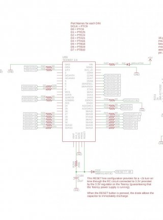
I tried connecting the reset line on the middle 5-pin header as shown in the attached image.

As I commented on my schematic, the intent was that the capacitor and resistor to the onboard 3.3V regulator would provide a soft turn on since this has reportedly been an issue with Teensy 3.6 boards in the past. The 3.3V regulator becomes active but the processor is kept in reset until everything is stable, and the diode ensures that if I push the chassis reset button it pulls the reset pin low.
Problem is that the actual voltage on the reset pin is around 1.4V despite the RESET signal being 3.3V measured on-board. Replacing the 200k pullup with a 10k didn't meaningfully help, but I see a periodic charge up and then discharge of the capacitor C180. In this configuration, it was impossible to communicate or program the Teensy. Removing R259, C180, and D19 caused the Teensy to turn on properly, but just removing D19 did not. The voltage at the 3V3 pin on the Teensy is fine.
I'm suspicious that the second chip on the Teensy is interfering from looking at the schematic, but I don't find ready documentation of that chip's behavior so I'm not clear on how it may be interfering. Am I misunderstanding what the RESET pin on the Teensy is for? I found people saying the second chip must be removed to use a debugger, which seems likely also related to reset lines, but I'd rather not be going in and removing that chip if it's needed to properly program the Teensy over USB.
What is the correct way to wire this to reset the Teensy with an external pushbutton?
I tried connecting the reset line on the middle 5-pin header as shown in the attached image.

As I commented on my schematic, the intent was that the capacitor and resistor to the onboard 3.3V regulator would provide a soft turn on since this has reportedly been an issue with Teensy 3.6 boards in the past. The 3.3V regulator becomes active but the processor is kept in reset until everything is stable, and the diode ensures that if I push the chassis reset button it pulls the reset pin low.
Problem is that the actual voltage on the reset pin is around 1.4V despite the RESET signal being 3.3V measured on-board. Replacing the 200k pullup with a 10k didn't meaningfully help, but I see a periodic charge up and then discharge of the capacitor C180. In this configuration, it was impossible to communicate or program the Teensy. Removing R259, C180, and D19 caused the Teensy to turn on properly, but just removing D19 did not. The voltage at the 3V3 pin on the Teensy is fine.
I'm suspicious that the second chip on the Teensy is interfering from looking at the schematic, but I don't find ready documentation of that chip's behavior so I'm not clear on how it may be interfering. Am I misunderstanding what the RESET pin on the Teensy is for? I found people saying the second chip must be removed to use a debugger, which seems likely also related to reset lines, but I'd rather not be going in and removing that chip if it's needed to properly program the Teensy over USB.
What is the correct way to wire this to reset the Teensy with an external pushbutton?

