Venus GPS integration with Teensy 2.0

Status
Not open for further replies.
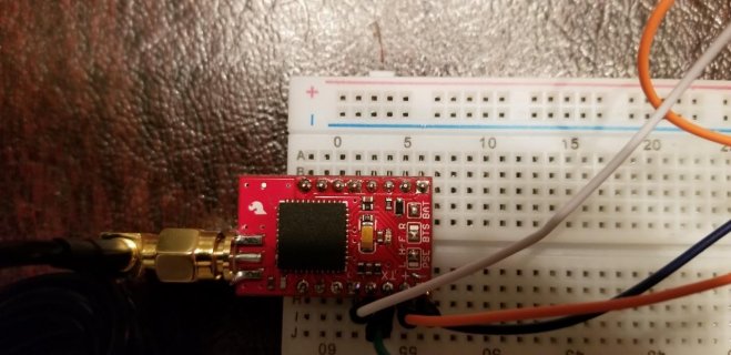
I am working on a project involving a Venus GPS. Currently I am having trouble reading anything from the GPS. I have installed the necessary GPS libraries and am going off Dr. Monk's tutorial based on the venus gps with an Arduino. I am using teensyduino to write the code via the Arduino software.

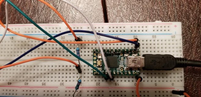
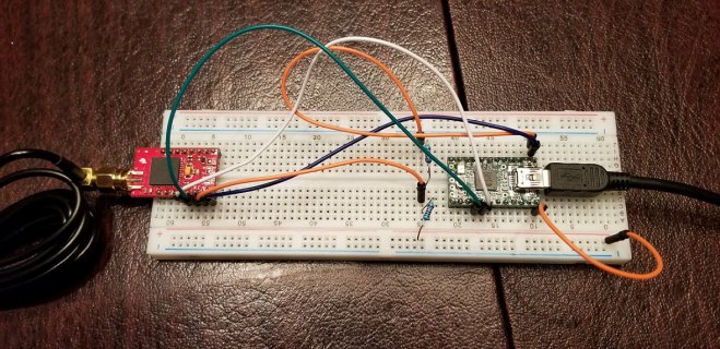
This is my first time using Teensy so I may be making a very dumb error. The GPS isn't fried and the LED will sometimes blink after uploading the code, however it does not stay lit. Because the Teensy 2.0 doesn't naturally output 3.3v, I am stepping down the voltage using a couple resistors. I think I was getting around 3.5v last time I measured it with a multimeter, but I would assume this is still within the allowable range. I have TX on the gps going to B5 on the Teesnsy, RX to B6 and GND to GND.

I am running the following script just to see if the gps was outputting anything, but nothing is printing on the serial monitor.
Here is the code (maybe I have the pins defined wrong?):


#include <SoftwareSerial.h>

SoftwareSerial gpsSerial(14,15); // RX, TX (TX not used)

void setup()
{
Serial.begin(9600);
gpsSerial.begin(9600);
}

void loop()
{
if (gpsSerial.available()>0)
{
Serial.write(gpsSerial.read());
}
}
 
This code looks like it should work. Maybe you don't actually have data arriving on pin 14?

If you want us to try to help, you've got to show what you've actually done. Photos are usually the best way to show how you've actually connected everything.

Would also help to have links for the specific products you're using and the tutorial you followed (we can't see your screen or workbench). A quick google search finds this link. Is this right?

https://www.sparkfun.com/products/11058
 
While I haven't used this particular GPS, I can tell you most of them automatically start ending a NEMA0183 data stream. So normally you only need to connect their transmit pin to Teensy's RX pin, and of course connect the ground pins. Usually a wire from TX on Teensy to RX on the GPS is not needed.
 
While I haven't used this particular GPS, I can tell you most of them automatically start ending a NEMA0183 data stream. So normally you only need to connect their transmit pin to Teensy's RX pin, and of course connect the ground pins. Usually a wire from TX on Teensy to RX on the GPS is not needed.

GPS: https://www.sparkfun.com/products/11058
GPS Antenna: https://www.amazon.com/Active-Anten...44812&sr=8-1-spons&keywords=gps+antenna&psc=1
Teensy Board: https://www.pjrc.com/store/teensy.html
 

Attachments

  • 20180317_203946.jpg
    20180317_203946.jpg
    120.8 KB · Views: 119
  • 20180317_203958.jpg
    20180317_203958.jpg
    90.6 KB · Views: 108
  • 20180317_203938.jpg
    20180317_203938.jpg
    387.4 KB · Views: 109
I see 2 problems.

First, do not connect the TX output from Teensy 2.0 directly to this GPS (the white wire). Teensy 2.0 will output 5V, but this GPS is not 5V tolerant. There's a chance this may damage the GPS.

Second, you need a real 3.3V power supply to power up the GPS. Using 2 resistors to divide the 5V power will not work. That only gives 3.3V without a load connected. When you connect something like this GPS in parallel with the lower resistor, the result will be less than 3.3V when the GPS tries to draw current. Resistor dividers only work when whatever you connect to the resistors uses very little current, relative to the amount of current flowing in the resistors. Sparkfun's page says this GPS uses 60 to 90 mA. You need a proper 3.3V power supply capable of delivering 90 mA.

Because your GPS hasn't been able to power up when connected this way, there's a good chance the 5V signal on the white wire may not have damaged the hardware. Maybe. I haven't used this particular GPS and I don't know anything about how it's designed. Just as a general way these sorts of things work, of course you shouldn't ever connect a 5V output signal to any 3.3V device that doesn't specifically say it's 5V tolerant, but often the damage happens when the device is powered up.

One other thing that isn't any issue in these photos, but you might like to know for later, is this appears to be one of the breadboards where the power rails are split. Many times we've had people post about strange problems here, where they appear to be doing everything correctly. Then the photos turn out have one of these breadboards where the power doesn't connect all the way across and the only thing wrong is the chips on the other side of their breadboard aren't getting power.

Also, when you get this working, using Serial1 instead of SoftwareSerial gives much better compatibility with other code & libraries. It should not make any difference for this small program, but if you build a more substantial program that does other stuff, just know SoftwareSerial has a lot of limitations and tends to interfere with other libraries. Serial1 is much better to use.
 
Status
Not open for further replies.
Back
Top