Battery Monitor Question

Status
Not open for further replies.

dereckbc

Well-known member
Hey back again wanting to start another project and foresee a couple of obstacles I thought I might run by you guys to get some feedback how to work around. I do a lot of RC Plane and Drone project work and I want to build a Battery Monitor to be able to read as many as 6 LiPo cells in series. But for the life of me having a brain fart on how to do it. I see two problems.

1. RC LiPo batteries come hard wired in series from 2S to 6S and equipped with a Balance Plug to allow direct access to individual cell voltages so they can be balanced by external circuitry. The A/D converter is referenced to a common point in the Teensy and I am clueless how I can decouple the the common rail so I can measure voltages of up to 6 cells wired in series without shorting the cells out. I know it can be done, but dang if I can figure it out.

2. Cell voltages will range from a low of 3 volts up to 4.3 volts which is outside the range of Teensy 3.3 volt limit. I need good accuracy. One thing I thought about is a Resistor Divider across each cell to scale down 4.3 volts to 3.3 volts but that adds error even if I were to use 1% resistors. Other thought and not sure it could be done is use an external 5 volt ADC somehow to feed to a Teensy. I would use an Ardiuno but the A/D resolution is too low.

I need a fair bit of accuracy as one thing I want this gizmo to do is measure each of the cells internal resistance with a LSB of .0001 Ohms. To do that I would use a Delta Voltage/Current method as it is the most accurate means to do that. Example apply say apply a Low Current Load of say 100 ma to the battery, read each cell voltage, and record the voltages. Then apply a 10-amp load and record cell voltages as low current. From there derive Delta Voltage/Current and apply Ohm's Law of R = V/I.

So can you help me please with some ideas? All comments welcome.

THX

Dereck
 
1. No real practical way of doing this unless you went to invest in a large array of relays with an isolated supply to power the Teensy.

2. Unless you invest in high accuracy resistors your going to be stuck with 1% resistors. The trick is to calibrate your adc channels with the offset and gain for each channel.

.0001Ohms at 10A is going to be 1mV. You will need some decent filtering and heavy oversampling on the Teensy or a higher resolution external ADC.

Kind of what I thought. Looks like a Differential ADC of 16 bits.
 
I'd highly suggest something like TI's INA219 if you haven't seen it. Even just as a way to rapid prototype/proof-of-concept that may be a good starting point. Adafruit make a breakout (https://www.adafruit.com/product/904) and Arduino library which would make it quite simple to get going. They're I2C so you can put a number of them on the same bus.
You'd run into issues with 10-amp measurements with the Adafruit board, though. You'd have to play around with the sense resistor value and Arduino library.
 
Having an EE background I've killed few years of my spare time on RC hobby (helicopters), and then another few years on electric bikes... There is no simple and clean high precision solution to your problem (but there are many half-decent approximate ones). The best you can do for really precise measurements is a set of individual MCU boards per parallel bank with true 12 bit ADCs connected via optical couplers to a TDM-like bus feeding a common controller - Teensy I assume :). You may find that designing and building a dozen of identical boards is easier and cheaper than a complex analog multiplexing circuit. And the distributed solution will be much more precise and flexible.
 
And the chain does not have to be optical (the most simple one requires 1 transistor and 1 resistor per module). The main point is to send the digital signal downward, not to multiplex analog voltage. Then you can build a BMS for hundreds volts with very high precision. The individual MCUs can be very slow and low power, but must have a quality single channel 12bit SAR ADC.
 
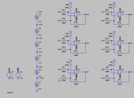
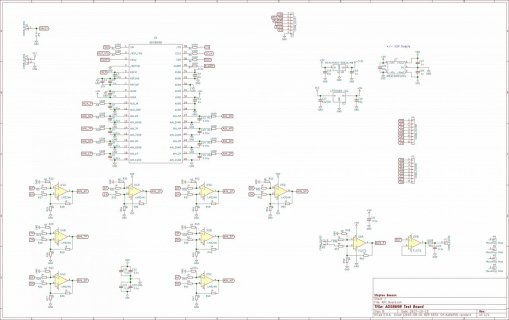
No reason why this should not work. Just hook it up to an ADC and your done. This could be done with the test board I created since I set up the dividers to be changeable between different configurations.

6CELL BATTERY MEASUREMENT.JPG
ADS8698 Breakout.jpg
Just make U7 a +/- 15V version instead of the +/- 12V and use decent opamps, the LM324 where placeholders. I used OPA4197's on the board I tested, very stable and accurate.
 
dereckbc - do you need a permanently connected BMS or a an accurate charge monitor ? In the later case the circuit above will work just fine. In the former case it will run the pack out of balance and eventually ruin it. There is no issue with 1% resistor accuracy, you can always calibrate the tool. The problem with the circuit above is uneven and significant discharge current for a permanent BMS.
 
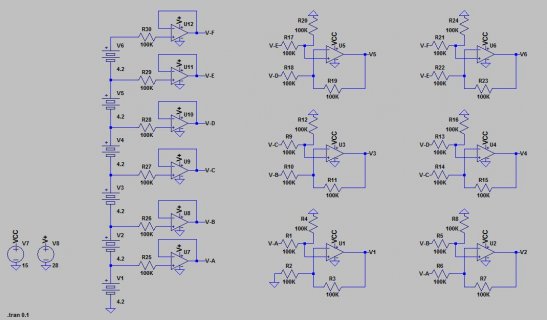
Correct as a battery monitor the circuit I provided would unbalance the pack. For the High accuracy resistance measurements it would be very good. Some of the uneven discharge could be adjusted by changing the resistor values of each section.I think instead adding a second op-amp at each measured voltage, then the only current would be the bias current of the op-amp inputs. That would require powering the first stage op-amps with voltage equal to or greater then the max pack voltage. Up to 32 volts is not to difficult, above that and op-amps become scarce. I may have a work around for the 32V limit, dereckbc only need 6 cell so that's not an issue for voltage.
 
Here is an updated basic schematic. There are Op-amps on the market that are rated for 36V continuous, that would be plenty for an 8S pack in case you want to future proof. As a BMS this is probably not the perfect solution, as part of a charge/balance controller it should provide pretty decent voltages. PS, most large scale BMS's are externally powered. One of the systems we are working with where I work is monitoring 11kW modules with 100Cells per module. The BMS is only active when external power is present.
If you keep the noise at a minimum and don't run things like SPI while taking measurements you can get =>13Bit resolution out of a Teensy with oversampling. You could run the output of the op-amps through a divider and filter (OV protection also) right to the Teensy.

6CELL BATTERY MEASUREMENT v2.JPG
 
Tried to load my chaining method circuit diagram in the .png format but got a strange cryptic error from the uploader. Oh well...
 
Status
Not open for further replies.
Back
Top