Hello,
I have a Teensy 3.5 that is powered from a USB cable (so it`s powered by 5V). I know that it has an internal LDO that converts 5V to 3.3V.
I am currently working on a project, a transimpedance amplifier for a photodiode to measure the LED illuminance. The output of the op-amp will be connected to one Analog pins of the Teensy. As we all know, this output MUST BE 3.3V maximum (because the pins are 3.3V tolerant), and this can be achieved by powering the op-amp at 3.3V and GND.
My question is:
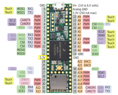
Can i use the pin between 12 and 24 (the 3.3V pin) to power the op-amp? From the datasheet, i can see that the op-amp draws a maximum of 0.5mA.

(the pin i`m talking about is the one with a yellow square)
I have a Teensy 3.5 that is powered from a USB cable (so it`s powered by 5V). I know that it has an internal LDO that converts 5V to 3.3V.
I am currently working on a project, a transimpedance amplifier for a photodiode to measure the LED illuminance. The output of the op-amp will be connected to one Analog pins of the Teensy. As we all know, this output MUST BE 3.3V maximum (because the pins are 3.3V tolerant), and this can be achieved by powering the op-amp at 3.3V and GND.
My question is:
Can i use the pin between 12 and 24 (the 3.3V pin) to power the op-amp? From the datasheet, i can see that the op-amp draws a maximum of 0.5mA.

(the pin i`m talking about is the one with a yellow square)

