ArtNet to WS2812 (directly via SPI)

Status
Not open for further replies.
Hello all,

I'm currently designing a matrix grid which consists out of two halves. The two halves each have 27 columns and 17 rows = 459 pixels.
So, the two halves together consists out of 54 columns and 17 rows, making a total of 918 pixels. (WS2812 pixels.)
These pixels all have 3 channels (Red, Green, Blue) making a respectable 918*3=2754 channels.

With 512 channels in a single universe, this makes that the entire matrix uses 6 universes (5.37890625 to be precise :p ).

In the end, the matrix(/matrices) will be controlled by software like Jinx! and/or a lighting controller like a GrandMa2, all via ArtNet.

Now, the actual question:

For the sake of being able to use the halves independent of each other, i'd like to give each halve a individual node (node/artnet controller, you name it). With the above mentioned calculations, this node should be able to control 459 pixels ( = 1377 channels, = 3 universes).

I've tried to do this with an arduino but find it to be a bit laggy. Some advices on other threads i've read advised people to use a Teensy instead.

Well, that's where the actual question comes in, does any of you have any experience or willing to help with designing the code for this to work?
Also, i'd prefer to use a ethernet cable over wireless as the device is going to be used in some public events.

Can anyone advice me in where to start, or point to any working code to be able to do this?

Also about hardware, how to make the ethernet connection, 3.3v // 5v problems, etc.

Thanks in advance!

A.


Crossposted on: https://forum.arduino.cc/index.php?topic=538225.0
 
Last edited:
Hello all,

I'm currently designing a matrix grid which consists out of two halves. The two halves each have 27 columns and 17 rows = 459 pixels.
So, the two halves together consists out of 54 columns and 17 rows, making a total of 918 pixels. (WS2812 pixels.)
These pixels all have 3 channels (Red, Green, Blue) making a respectable 918*3=2754 channels.

With 512 channels in a single universe, this makes that the entire matrix uses 6 universes (5.37890625 to be precise :p ).

In the end, the matrix(/matrices) will be controlled by software like Jinx! and/or a lighting controller like a GrandMa2, all via ArtNet.

Now, the actual question:

For the sake of being able to use the halves independent of each other, i'd like to give each halve a individual node (node/artnet controller, you name it). With the above mentioned calculations, this node should be able to control 459 pixels ( = 1377 channels, = 3 universes).

I've tried to do this with an arduino but find it to be a bit laggy. Some advices on other threads i've read advised people to use a Teensy instead.

Well, that's where the actual question comes in, does any of you have any experience or willing to help with designing the code for this to work?
Also, i'd prefer to use a ethernet cable over wireless as the device is going to be used in some public events.

Can anyone advice me in where to start, or point to any working code to be able to do this?

Also about hardware, how to make the ethernet connection, 3.3v // 5v problems, etc.

Thanks in advance!

A.


Crossposted on: https://forum.arduino.cc/index.php?topic=538225.0


I am controlling 32 universes with one teensy 3.2 using SACN. Just got my site up with links and info to code and hardware http://megapixel.lighting

Here is 1600 Pixels

https://youtu.be/l3cA2Wv3P_k
 
Thanks for your reply!

For now i'm trying to make something myself, if this won't work out I could always consider buying your solution. Thanks for the info anyhow!

My thought is that it shouldn't be too hard to achieve my goals.

I'm curious about using the code supplied in this example:
https://github.com/PaulStoffregen/OctoWS2811/blob/master/examples/Artnet/Artnet.ino

Has any of you used this with an ethernet connection?
And, can't seem to find which port is used for data output to the LED's in this code?

Thanks in advance!


The code uses the wiznet module for network connectivity https://www.pjrc.com/store/wiz820_sd_adaptor.html

for info on ports or pinout https://www.pjrc.com/store/octo28_adaptor.html

This code sample uses the octows2811 library. This library has set pins defined to it. you can look at the Octws2811 adapter in the store and it will show the pins being used. One thing to keep in mind is how your going to connect the teensy to your pixels. Its a science if you don't use the octows2811 board or the boards like the one on megapixel.lighting. The reason is these boards have the level shifter IC to help with ws281x signalling (teensy is 3.3v and pixels want 5v) plus they have some resistors to help with impedance. without it your Mileage may vary and results will be uncertain.
 
I have used the code. What many find is that you start to run into issues after 2-3 universes. Your issues start to happen when the Ethernet buffer fills up. Look for my posts and you can read up on the challenges and success.
 
Thanks for the great help!
About the code i mentioned, it doesn't use the SD card actually, does it? As i do have a W5500 (and OctoWS2811) lying around, would it also be OK to just connect the teensy to the OctoWS2811 and the W5500?
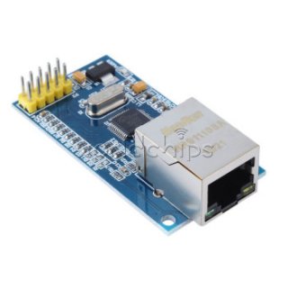
And, i've currently have this type of w5500 (see image), am i abled to attach it without a seperate level shifter (as i don't have one lying around)?

spidan-ethernettcpip-donusturucu-w5500-usr-es1-11727-43-K.jpg


Thanks in advance!
 
Awesome you have the parts! I will have to check but see if the octows2811 has the pins available that you can connect to the w5500. If not you can put the teensy in a bread board and use pins to connect it to the ethernet module and the octo shield. I did this before I prototype my boards.
 
So, i can use the code without the SD part and the individual level shifter (as i don't have these parts yet) ?

Thanks in advance for checking, looking forward to hear from you!
 
And, if yes, do you know what the wiring of the components should be? Can't really find out how to connect both the w5500 and the OctoWS2811 simultaniously.
Thanks in advance!
 
I´m currently using this code with an Arduino Uno and a W5100, but unfortunately, the device isn´t receiving more than 1 universe.

With <170 LEDs the code/setup works great with Jinx!, no problems at all, however:

When i set the num_Leds to a value above 170, the device won't even run the inittest() anymore.
To eliminate any problems in the inittest void which would prevent the arduino to complete initialization/setup, i've also tried with the inittest commented out but unfortunately this doesn't work.

I'm driving the Leds with Jinx! with the device settings as seen in the attached image.

Does any of you see any problems/errors in the code? The original code comes from:
https://github.com/natcl/Artnet/blob/master/examples/NeoPixel/ArtnetNeoPixel/ArtnetNeoPixel.ino

The code i'm currently using is:

Code:
/*
This example will receive multiple universes via Artnet and control a strip of ws2811 leds via 
Adafruit's NeoPixel library: https://github.com/adafruit/Adafruit_NeoPixel
This example may be copied under the terms of the MIT license, see the LICENSE file for details
*/

#include <Artnet.h>
#include <Ethernet.h>
#include <EthernetUdp.h>
#include <SPI.h>
#include <Adafruit_NeoPixel.h>

// Neopixel settings
const int numLeds = 170; // change for your setup
const int numberOfChannels = numLeds * 3; // Total number of channels you want to receive (1 led = 3 channels)
const byte dataPin = 2;
Adafruit_NeoPixel leds = Adafruit_NeoPixel(numLeds, dataPin, NEO_RGB + NEO_KHZ800);

const int dtS = 12; //750/numLeds; // Short delay time (used for test/boot program)
const int dtL = 750; // Long delay time (used for test/boot program)
const int delayLeds = 10; // Amount of leds to be on simultaniously in last step of inittest()

// Artnet settings
Artnet artnet;
const int startUniverse = 0; // CHANGE FOR YOUR SETUP most software this is 1, some software send out artnet first universe as 0.

// Check if we got all universes
const int maxUniverses = numberOfChannels / 512 + ((numberOfChannels % 512) ? 1 : 0);
bool universesReceived[maxUniverses];
bool sendFrame = 1;
int previousDataLength = 0;

// Change ip and mac address for your setup
byte ip[] = {192,168,178,77};
byte mac[] = {0x04, 0xE9, 0xE5, 0x00, 0x69, 0xEC};
byte broadcast[] = {10, 0, 1, 255};
void setup()
{
 *//Serial.begin(115200);
 *artnet.begin(mac, ip);
 *leds.begin();
 *artnet.setBroadcast(broadcast);
 *initTest();

 *// this will be called for each packet received
 *artnet.setArtDmxCallback(onDmxFrame);
}

void loop()
{
 *// we call the read function inside the loop
 *artnet.read();
}

void onDmxFrame(uint16_t universe, uint16_t length, uint8_t sequence, uint8_t* data)
{
 *sendFrame = 1;
 *// set brightness of the whole strip 
 *if (universe == 15)
 *{
 * *leds.setBrightness(data[0]);
 * *leds.show();
 *}

 *// Store which universe has got in
 *if ((universe - startUniverse) < maxUniverses)
 * *universesReceived[universe - startUniverse] = 1;

 *for (int i = 0 ; i < maxUniverses ; i++)
 *{
 * *if (universesReceived[i] == 0)
 * *{
 * * *//Serial.println("Broke");
 * * *sendFrame = 0;
 * * *break;
 * *}
 *}

 *// read universe and put into the right part of the display buffer
 *for (int i = 0; i < length / 3; i++)
 *{
 * *int led = i + (universe - startUniverse) * (previousDataLength / 3);
 * *if (led < numLeds)
 * * *leds.setPixelColor(led, data[i * 3], data[i * 3 + 1], data[i * 3 + 2]);
 *}
 *previousDataLength = length; * * 
 *
 *if (sendFrame)
 *{
 * *leds.show();
 * *// Reset universeReceived to 0
 * *memset(universesReceived, 0, maxUniverses);
 *}
}

void initTest()
{
 *for (int i = 0 ; i < numLeds ; i++)
 * *leds.setPixelColor(i, 127, 0, 0);
 *leds.show();
 *delay(dtL);
 *for (int i = 0 ; i < numLeds ; i++)
 * *leds.setPixelColor(i, 0, 127, 0);
 *leds.show();
 *delay(dtL);
 *for (int i = 0 ; i < numLeds ; i++)
 * *leds.setPixelColor(i, 0, 0, 127);
 *leds.show();
 *delay(dtL);

 * *for (int i = 0 ; i < numLeds ; i++)
 * *leds.setPixelColor(i, 0, 0, 0);
 *leds.show();
 *
 *for (int i = 0 ; i < numLeds+delayLeds ;){
 * *leds.setPixelColor(i-delayLeds, 0, 0, 0);
 * *leds.setPixelColor(i, 100, 0, 0);
 * *leds.show();
 * *delay(dtS);
 * *i++;
 *}

 *for (int i = 0 ; i < numLeds+delayLeds ;){
 * *leds.setPixelColor(i-delayLeds, 0, 0, 0);
 * *leds.setPixelColor(i, 0, 100, 0);
 * *leds.show();
 * *delay(dtS);
 * *i++;
 *}

 * *for (int i = 0 ; i < numLeds+delayLeds ;){
 * *leds.setPixelColor(i-delayLeds, 0, 0, 0);
 * *leds.setPixelColor(i, 0, 0, 100);
 * *leds.show();
 * *delay(dtS);
 * *i++;
 *}

 * *for (int i = 0 ; i < numLeds+delayLeds ;){
// * *leds.setPixelColor(i-delayLeds, 0, 0, 0);
 * *leds.setPixelColor(i, 255, 255, 255);
 * *leds.show();
 * *delay(dtS);
 * *i++;
 *}
 *delay(2000);
// * * *for (int i = 0 ; i < numLeds+delayLeds ;){
// * *leds.setPixelColor(i-delayLeds, 0, 0, 0);
// * *leds.setPixelColor(i, 0, 0, 100);
// * *leds.show();
// * *delay(dtS);
// * *i++;
// *}


 *for (int i = 0 ; i < numLeds ; i++)
 * *leds.setPixelColor(i, 0, 25, 0);
 *leds.show();
 *
}
 
Just before the weekend my Octows2811 SD/Ethernet adaptor board arrived so I immediately went to assemble them to my Teensy 3.2 and tested it.

Currently, also with the OctoWS2811, i'm still abled to only let 170 leds be controlled simultaniously.
I've uploaded the 'BasisTest' example from 'PaulStoffRegen', and adapted it a bit (number of leds, etc.) to fit my setup.

When entering more than 170 LEDs and uploading the code, nothing happens on the LEDs, they all stay 'black'.
When entering 170 LEDs or less, the code runs fine and the correct amount of LEDs light up according to the test loop.

The same thing happen with the ArtNet example.

To eliminate any minor mistakes or typos in my used code, i'll copy-paste the code from the IDE below.

Does any of you have any clue on how to get more than 170 LEDs driven/controlled?

For information, all LEDs (currently 204 pcs) are in series (regarding the data line), fed from the orange+orangewhite cable from the RJ45 connector in the OctoWS2811 as mentioned in this page.
Power is supplied to each column of 17 LEDs separately from common + and - rails.

Thanks in advance.
A.


Code:
/*  OctoWS2811 BasicTest.ino - Basic RGB LED Test
    http://www.pjrc.com/teensy/td_libs_OctoWS2811.html
    Copyright (c) 2013 Paul Stoffregen, PJRC.COM, LLC

    Permission is hereby granted, free of charge, to any person obtaining a copy
    of this software and associated documentation files (the "Software"), to deal
    in the Software without restriction, including without limitation the rights
    to use, copy, modify, merge, publish, distribute, sublicense, and/or sell
    copies of the Software, and to permit persons to whom the Software is
    furnished to do so, subject to the following conditions:

    The above copyright notice and this permission notice shall be included in
    all copies or substantial portions of the Software.

    THE SOFTWARE IS PROVIDED "AS IS", WITHOUT WARRANTY OF ANY KIND, EXPRESS OR
    IMPLIED, INCLUDING BUT NOT LIMITED TO THE WARRANTIES OF MERCHANTABILITY,
    FITNESS FOR A PARTICULAR PURPOSE AND NONINFRINGEMENT. IN NO EVENT SHALL THE
    AUTHORS OR COPYRIGHT HOLDERS BE LIABLE FOR ANY CLAIM, DAMAGES OR OTHER
    LIABILITY, WHETHER IN AN ACTION OF CONTRACT, TORT OR OTHERWISE, ARISING FROM,
    OUT OF OR IN CONNECTION WITH THE SOFTWARE OR THE USE OR OTHER DEALINGS IN
    THE SOFTWARE.

  Required Connections
  --------------------
    pin 2:  LED Strip #1    OctoWS2811 drives 8 LED Strips.
    pin 14: LED strip #2    All 8 are the same length.
    pin 7:  LED strip #3
    pin 8:  LED strip #4    A 100 ohm resistor should used
    pin 6:  LED strip #5    between each Teensy pin and the
    pin 20: LED strip #6    wire to the LED strip, to minimize
    pin 21: LED strip #7    high frequency ringining & noise.
    pin 5:  LED strip #8
    pin 15 & 16 - Connect together, but do not use
    pin 4 - Do not use
    pin 3 - Do not use as PWM.  Normal use is ok.

  This test is useful for checking if your LED strips work, and which
  color config (WS2811_RGB, WS2811_GRB, etc) they require.
*/

#include <OctoWS2811.h>

const int ledsPerStrip = 204;

DMAMEM int displayMemory[ledsPerStrip*6];
int drawingMemory[ledsPerStrip*6];

const int config = WS2811_GRB | WS2811_800kHz;

OctoWS2811 leds(ledsPerStrip, displayMemory, drawingMemory, config);

void setup() {
  leds.begin();
  leds.show();
}

#define RED    0xFF0000
#define GREEN  0x00FF00
#define BLUE   0x0000FF
#define YELLOW 0xFFFF00
#define PINK   0xFF1088
#define ORANGE 0xE05800
#define WHITE  0xFFFFFF

// Less intense...
/*
#define RED    0x160000
#define GREEN  0x001600
#define BLUE   0x000016
#define YELLOW 0x101400
#define PINK   0x120009
#define ORANGE 0x100400
#define WHITE  0x101010
*/

void loop() {
  int microsec = 2000000 / leds.numPixels();  // change them all in 2 seconds

  // uncomment for voltage controlled speed
  // millisec = analogRead(A9) / 40;

  colorWipe(RED, microsec);
  colorWipe(GREEN, microsec);
  colorWipe(BLUE, microsec);
  colorWipe(YELLOW, microsec);
  colorWipe(PINK, microsec);
  colorWipe(ORANGE, microsec);
  colorWipe(WHITE, microsec);
}

void colorWipe(int color, int wait)
{
  for (int i=0; i < leds.numPixels(); i++) {
    leds.setPixel(i, color);
    leds.show();
    delayMicroseconds(wait);
  }
}
 
if you are running the standard octows test with the 3.2 (i.e not doing anything with ArtNEt) as you can get it to light more than 170 leds, I think that there is something wrong with the setup other than buffers. This simple teensy plus octo adapter board plus leds using the basic test should run hundreds of leds without issue. Check wiring connections again, ensure that enough power is going to the leds (are you using an external power supply?). It should just work with this sketch as you are not receiving data from anywhere other than generated within the sketch.
 
Hi,

Thanks for your reply.

The reason i've used the BasicTest example is indeed to eliminate any other complex/possible issues regarding for example the artnet configuration.
I've already double-checked all wiring, but can't seem to find any issue. Everything is connected in a professional way, each string of 17 is supplied by a separate power line. The complete matrix (currently 204 pixels) is powered by a 30A rated lab power supply.

Anyways, with all the leds attached (204pcs), and setting a amount of 170 pixels in the BasicTest sketch, these 170 pixels work fine with the test (even with an artnet sketch they work fine). However, when changing the number of 170 to 204 in the sketch, upload it to the teensy, none of the leds go on anymore. Changing it back to 170pixels makes the leds work fine again.
This makes me suspect just some coding/teensy/octows2811 problems...

Hope someone can help me with this.
Thanks!
 
sounds like a tough one to find. You could try using the basic FastLed (FirstLight sketch) and setting the pin to 1 or 5 (I think that those are the corresponding orange data pins) without having to rewire anything . If you find that you can get more than 170 leds going, it may narrow down the cause.
 
Thanks for your reply!


Good one about the testing with a basic fastled setup, gonna do that this evening!

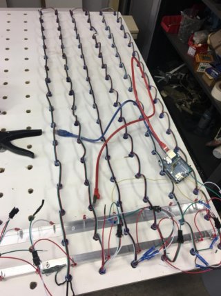
I've attached a photo of the wiring setup, keep in mind this is an old photo with just several columns done yet. I'll upload a new and clearer image when i'm home this evening.

IMG_FewStrips.jpg

A.
 
Hi all,

After some time the receivement of >170 Pixels worked, although i can't really find out why it does now and didn't before.
End good all good.

But offcourse the project continues, so next up i would like to make some improvements to the code:

1. It would be great to have a status LED blink or RGB LED have a specific color, according to the several states. This LED would be mounted on the backside or somewhere, for example near to the data and power connections of the cabinet.
For example:
State01: Power on = RED
State02: Power on but not receiving artnet data = Orange
State03: Power on and receiving artnet data = Green
Another way would be to use some blink-patterns with just one regular LED

2. Adjust settings through network portal/webservice.
First thought: After pressing a dedicated 'Hard Reset button' (not the general reset button of the teensy), the IP adress gets set to a specific default address (For example 1.2.3.4) Now, with some browser one can go to the default IP address (1.2.3.4.) and enter new data/setup for the device.
Other settings/options in the portal would be:
- Do soft reset
- Set number of pixels
- Set gamma correction?
- Set max brightness level?
- Light up individual pixels (for patching and debugging ease/example)?
- Select mode (and define as default)
- Do hard reset (as described above)
-

3. Multiple mode apart from receiving artnet, like doing some stand-alone animations or facilitate simple games (how cool would it be to do a pong-game on such a large pixelscreen!) Modes can be chosen by accessing the network portal.


It would be great if any of you has any ideas on the above mentioned improvements.
Looking forward to hear about your thoughts.

Thanks in advance!
A.
 
regarding point one, a status led, you can use a single through hole 5mm rgb led with four pins (RGB cathode). I have used these a number of time for performers to know which mode their little black box of tricks is currently in.

Depends on how many pins you have available and want to avoid any library function clashes by trying to use led libraries for addressable rgb leds. Using this approach you can add in a state variable that changes value given the mode you are in, this value is checked through the loop, and then you can you Case or If function to set pins high or low. You can also add in a millis() with another state that keeps track of whether the led is on or off, and changes this state alternately so that flashes the led for the given state. See blink without delay for the last part. This way you have many colour options and blink pattern to increase you visual representation of mode and activity.
 
Thanks for your reply!

I think the status led will be no problem, only have to figure out/search when/which event to trigger the LED, so in which part of the code.

Most questions i have are in number 2 and 3. Does anybody have any ideas to help me with this?

Thanks in advance!
 
Status
Not open for further replies.
Back
Top