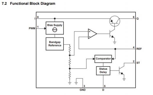
TL4242 is a constant current LED driver IC. I am confused by the "Constant Current".
If there is a PWM input at Pin1, then the output Pin6 is PWM? If there is a shunt resistor at Pin 4, this pin is also PWM? How does TL4242 control the brightness according to the block diagram?
My thought is: if LED is working at constant current, Pin6 and Pin4 are constant voltage outputs so the current is also constant. But how a PWM signal can generate a constant voltage output? It looks like there is internal linear voltage/current regulator?


