Hello.
I have an issue at work with a safety controller that is going into an undocumented fault state.
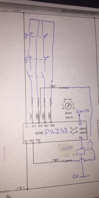
Its a little yellow module that monitors a few e-stop switches and opens a set of contacts when the e-stop contacts are open, or shorted.
The problem is when I'm called to look at the fault I arrive to the controller in an impossible state (power,in1,in2,reset indicating lights on but Out light and fault light off).

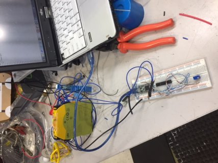
I finally had an excuse to pull out a teensy3.2 , and with a transistor and resistor created a device to open a channel for pot adjustable amount of time.
I found that I can only put this device (pilz PNOZ S3) in the particular state if I open a e-stop contact for >9ms (anything below is ignored) or <35ms (anything above correctly triggers fault light).

The only data logger we have at work has a 25hz refresh on a few analog signals so wouldn't even catch this condition.
I doubt I'll need it for this issue , but I am interested in building a "glitch catcher" that would need to monitor 24vdc signals and log data at a high enough rate to capture this type of issue.
I've been thinking and I only ever need low resolution data (maybe 8bit 0v - 25.5vdc at .1v steps) and would only need to timestamp log when data changes by .1Vdc.
I think a 1Mohm voltage divider with 3.3V zener diode at the teensy input to protect from spikes?
Maybe a simple voltage divider with zener for supplying power to teensy.
I'm just after some thoughts on what others have done for data logging and some guidance on my teensy protection method or any other issues I might not have thougth of. My electronics is very basic.
Thanks.
I have an issue at work with a safety controller that is going into an undocumented fault state.
Its a little yellow module that monitors a few e-stop switches and opens a set of contacts when the e-stop contacts are open, or shorted.
The problem is when I'm called to look at the fault I arrive to the controller in an impossible state (power,in1,in2,reset indicating lights on but Out light and fault light off).

I finally had an excuse to pull out a teensy3.2 , and with a transistor and resistor created a device to open a channel for pot adjustable amount of time.
I found that I can only put this device (pilz PNOZ S3) in the particular state if I open a e-stop contact for >9ms (anything below is ignored) or <35ms (anything above correctly triggers fault light).

Code:
#include <SPI.h>
#include <gpio_MCP23S17.h>

//define CS pin and using HAEN or not
//to use HAEN, address should be 0x20 to 0x27
gpio_MCP23S17 mcp(10,0x20);//instance (address A0,A1,A2 tied to +)

void setup(){
  mcp.begin();//x.begin(1) will override automatic SPI initialization
  mcp.gpioPinMode(OUTPUT);
  //mcp.portPullup(HIGH);
  mcp.gpioPort(0xFFFF);
}
uint32_t potValue=0;
#define TEST_TIME 2000
elapsedMillis testTime=0;
void loop(){
  potValue=analogRead(14)*100;
  if(testTime>TEST_TIME)
  {
    //potValue*=100;
    Serial.print("open circuit for : ");
    Serial.print(potValue);
    Serial.println(" Microseconds.");
    testTime=0;
    mcp.gpioPort(0x0000);
    uint32_t tempTime=micros();

    while(micros()<(tempTime+potValue))
    {}                                  //delay for uSeconds set by pot.

    mcp.gpioPort(0xFFFF);
    Serial.println("circuit closed again");
  }
 Serial.println(potValue);
 delay(200);
}
The only data logger we have at work has a 25hz refresh on a few analog signals so wouldn't even catch this condition.
I doubt I'll need it for this issue , but I am interested in building a "glitch catcher" that would need to monitor 24vdc signals and log data at a high enough rate to capture this type of issue.
I've been thinking and I only ever need low resolution data (maybe 8bit 0v - 25.5vdc at .1v steps) and would only need to timestamp log when data changes by .1Vdc.
I think a 1Mohm voltage divider with 3.3V zener diode at the teensy input to protect from spikes?
Maybe a simple voltage divider with zener for supplying power to teensy.
I'm just after some thoughts on what others have done for data logging and some guidance on my teensy protection method or any other issues I might not have thougth of. My electronics is very basic.
Thanks.

