Epyon
Well-known member
I need to measure the load angle of a generator set, which is the angle between the mechanical rotor position and the electric waveform applied to the windings of the stator. To achieve this I need to make a rotary position measurement of the machine axle, with the measurement exactly synchronised to the (slightly varying) period of the AC voltage that is being applied to the machine windings. So from the perspective of the waveform, the position measurement is always happening at the same 'place'.
Voltage measurement is done through a differential probe, which gives me a differential signal that I can connect to the Teensy analog inputs. Position measurement is done through an absolute encoder, which is connected to the Teensy over RS-422 (SSI).

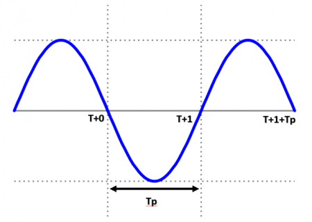
I was thinking of using pedvides ADC lib to take continuous, equidistant (e.g. every 200µs, through interrupts) differential samples of the waveform to detect a positive-to-negative zero crossing. When a zero crossing is detected (the ADC value changes sign), the micros() value would be saved as T0. Then the next few samples are analysed to check if it is a 'real' zero crossing and not a false positive because of harmonic distortion (noise) of the waveform (if it's a false positive, the micros() value gets reset).
The same thing happens on the negative to positive crossing, yielding T+1. Subtracting both micros() values allows me to determine the period of the waveform Tp.
After a time period Tp (or a constant fraction of it, it doesn't really matter as long as it is on the same position in each waveform), the Teensy triggers the encoder and receives the position information. This takes around 270µs. The AC waveform itself has a frequency of 50Hz +/-1.5Hz.
I'm not sure how to make the timing work. The analog sampling should probably be done in interrupts, and then after period Tp has been determined these interrupts should be disabled to allow proper triggering of the encoder and receiving and decoding its serial output (so without it being disrupted by the sampling interrupt). I hope an elapsedMicros() in the loop() will be accurate enough to give the trigger. After this has been done, interrupts can be enabled again and the cycle repeated.
Is this a sane approach? Any pitfalls? Or am I missing a much easier way to accomplish this?
Voltage measurement is done through a differential probe, which gives me a differential signal that I can connect to the Teensy analog inputs. Position measurement is done through an absolute encoder, which is connected to the Teensy over RS-422 (SSI).

I was thinking of using pedvides ADC lib to take continuous, equidistant (e.g. every 200µs, through interrupts) differential samples of the waveform to detect a positive-to-negative zero crossing. When a zero crossing is detected (the ADC value changes sign), the micros() value would be saved as T0. Then the next few samples are analysed to check if it is a 'real' zero crossing and not a false positive because of harmonic distortion (noise) of the waveform (if it's a false positive, the micros() value gets reset).
The same thing happens on the negative to positive crossing, yielding T+1. Subtracting both micros() values allows me to determine the period of the waveform Tp.
After a time period Tp (or a constant fraction of it, it doesn't really matter as long as it is on the same position in each waveform), the Teensy triggers the encoder and receives the position information. This takes around 270µs. The AC waveform itself has a frequency of 50Hz +/-1.5Hz.
I'm not sure how to make the timing work. The analog sampling should probably be done in interrupts, and then after period Tp has been determined these interrupts should be disabled to allow proper triggering of the encoder and receiving and decoding its serial output (so without it being disrupted by the sampling interrupt). I hope an elapsedMicros() in the loop() will be accurate enough to give the trigger. After this has been done, interrupts can be enabled again and the cycle repeated.
Is this a sane approach? Any pitfalls? Or am I missing a much easier way to accomplish this?

